
Pressure reducing valve and temperature-reducing and pressure-reducing device

A technology of temperature reduction, pressure reduction and pressure reducing valve, which is applied in the direction of the valve device, the device for absorbing fluid energy of the valve, the lifting valve, etc., which can solve the problems of high noise and achieve the effect of reducing vibration

Inactive Publication Date: 2012-07-11
HANGZHOU WORLDWISE VALVE
View PDF5 Cites 2 Cited by
  • Summary
  • Abstract
  • Description
  • Claims
  • Application Information

AI Technical Summary

Problems solved by technology

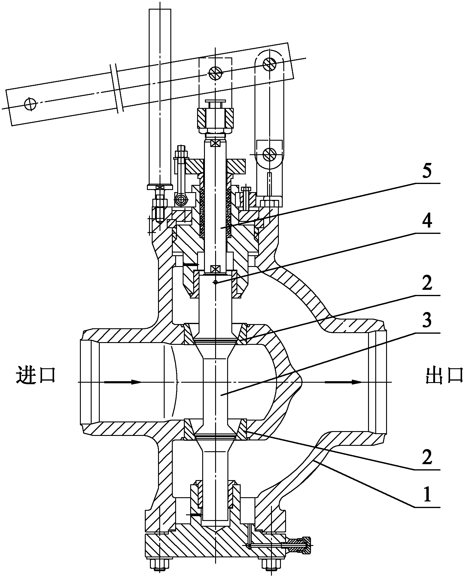
When the traditional pressure reducing valve completes the opening and closing action, it relies on the actuator to provide power. When the actuator provides power, it will produce a certain vibration, which will cause the valve stem 5 connected to the actuator to generate vibration in its radial direction. Unnecessary movement, when the valve stem 5 moves radially upwards, it collides with its surrounding parts, resulting in high noise generation

Method used


Image

  • Pressure reducing valve and temperature-reducing and pressure-reducing device
  • Pressure reducing valve and temperature-reducing and pressure-reducing device
  • Pressure reducing valve and temperature-reducing and pressure-reducing device

Examples


Embodiment Construction

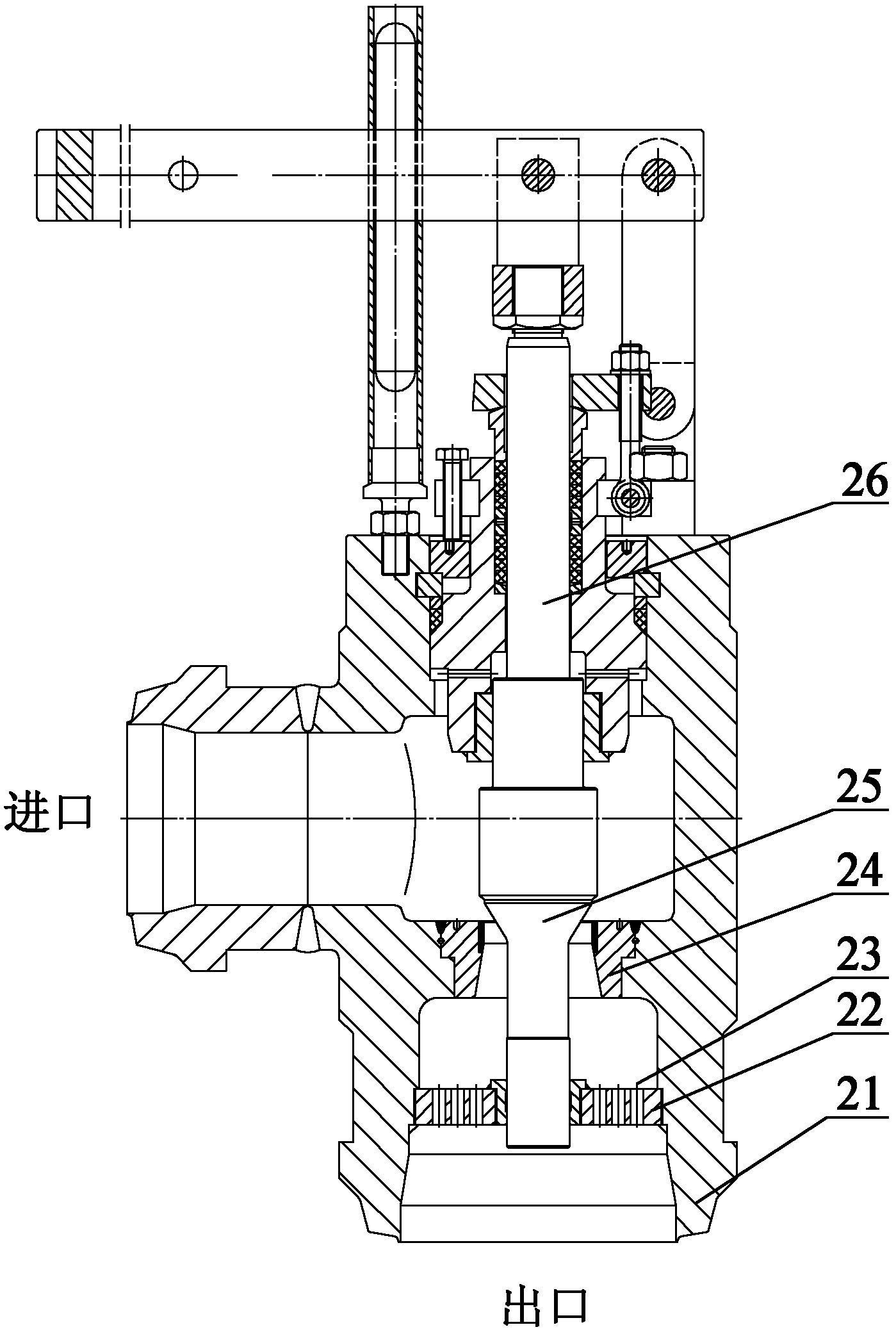
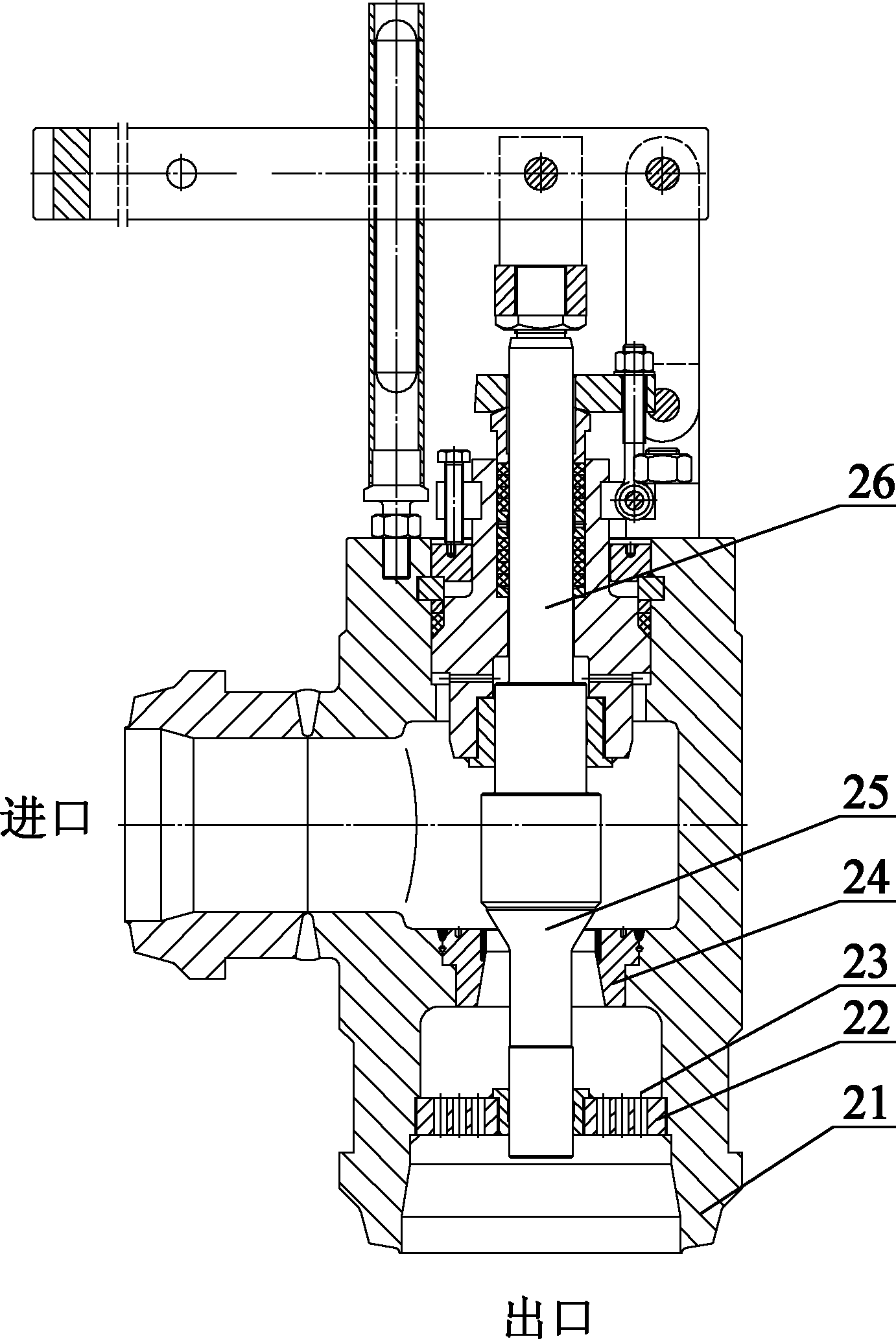
[0021] The embodiment of the present invention provides a pressure reducing valve and a temperature reducing and pressure reducing device, which can reduce the vibration of the valve disc and reduce the noise to make the working environment quieter.

[0022] The following will clearly and completely describe the technical solutions in the embodiments of the present invention with reference to the accompanying drawings in the embodiments of the present invention. Obviously, the described embodiments are only part of the embodiments of the present invention, not all of them. Based on the embodiments of the present invention, all other embodiments obtained by persons of ordinary skill in the art without making creative efforts belong to the protection scope of the present invention.

[0023] as attached figure 2 as shown, figure 2 Schematic diagram of the structure of the pressure reducing valve provided by the embodiment of the present invention.

[0024] The pressure reduci...


PUM


Abstract

The invention provides a pressure reducing valve and a temperature-reducing and pressure-reducing device. The pressure reducing valve comprises a valve body, valve seats, a valve flap and a valve rod and also comprises a guide cover, wherein the valve seats are fixedly connected with the valve body; the valve flap moves in the valve seat to change the flow areas of the valve seats; the valve rod is connected with the valve flap; the guide cover is sheathed on the valve flap; the two ends of the guide cover abut against the inner wall of the valve body; the guide cover is provided with a flow guiding hole, and is sheathed on the valve flap; the two ends of the guide cover abut against the inner wall of the valve body respectively; and the actuating mechanism drives the valve rod connected with the actuating mechanism to move and further drive the valve flap to move in the valve seats and the guide cover. The invention has the advantages that the radial movement of the valve flap is effectively limited by adopting a mode that the guide cover is sheathed on the valve flap, the valve flap finishes the axial movement better, and the unnecessary radial movement of the valve flap is limited, so that the vibration of the valve flap is reduced, and further the noise is reduced to enable the working environment to be quiet; and steam flowing out of the valve seats flows out of the flow guiding hole arranged in a guide sleeve, is guided out of the flow guiding hole, and is also throttled simultaneously, so that the action of secondary pressure reduction is achieved.

Description

technical field [0001] The invention relates to the technical field of boilers, more specifically, to a pressure reducing valve and a temperature and pressure reduction device. Background technique [0002] Large-capacity, high-parameter, diversified and automated boilers are used in industrial fields such as coal-to-oil and thermal power units. The steam generated by the boiler needs to be treated by a temperature and pressure reduction device to meet the requirements of the process system. The core component of the temperature and pressure reduction device is the pressure reducing valve. The traditional pressure reducing valve includes valve body 1, valve seat 2, valve disc 3, round pin 4 and valve stem 5 and other components. The traditional pressure reducing valve relies on the actuator to drive the movement of the valve stem 5 connected to it. The valve stem 5 drives the valve disc 3 fixedly linked to it through the round pin 4 to move in the valve seat 2, and the valve...

Claims


Application Information

Patent Timeline
IPC IPC(8): F16K47/08F16K1/32F16K27/02
Inventor 陈立龙刘儒亚陈荣斌张明王晖虞闻斌
Owner HANGZHOU WORLDWISE VALVE
Learn More