Winding machine and winding method

A wire winding method and wire winding technology, which are applied in the direction of electromechanical devices, manufacturing motor generators, electrical components, etc., can solve the problems of side plate 202 entry, short distance, wire guide, etc., and achieve the effect of stable and neat winding

Inactive Publication Date: 2012-07-11
NITTOKU ENG CO LTD
View PDF10 Cites 7 Cited by
  • Summary
  • Abstract
  • Description
  • Claims
  • Application Information

AI Technical Summary

Problems solved by technology

Then when wanting to continue to wind the second layer on the first layer winding that has been wound on the magnetic pole 201, the top of the side plate 202 will be in contact with the first layer, so that when the second layer winding is carried out, it cannot be used. The side plate 202 enters the inner peripheral side of the magnetic pole 201
And when it is desired to carry out the third layer of winding, the top of the side plate 202 will also be in contact with the second layer, so that the distance for the side plate 202 to enter the inner peripheral side of the magnetic pole 201 becomes shorter
In this way, along with the winding of the upper layer, the entry distance of the side plate 202 will be shortened successively, thereby leaving the problem that the inner peripheral side cannot guide the wire to the part where the winding is originally intended to be performed in the winding of the upper layer. topic

Method used


Image

  • Winding machine and winding method
  • Winding machine and winding method
  • Winding machine and winding method

Examples


Embodiment Construction

[0049] Hereinafter, the best mode for carrying out the present invention will be described based on the drawings.

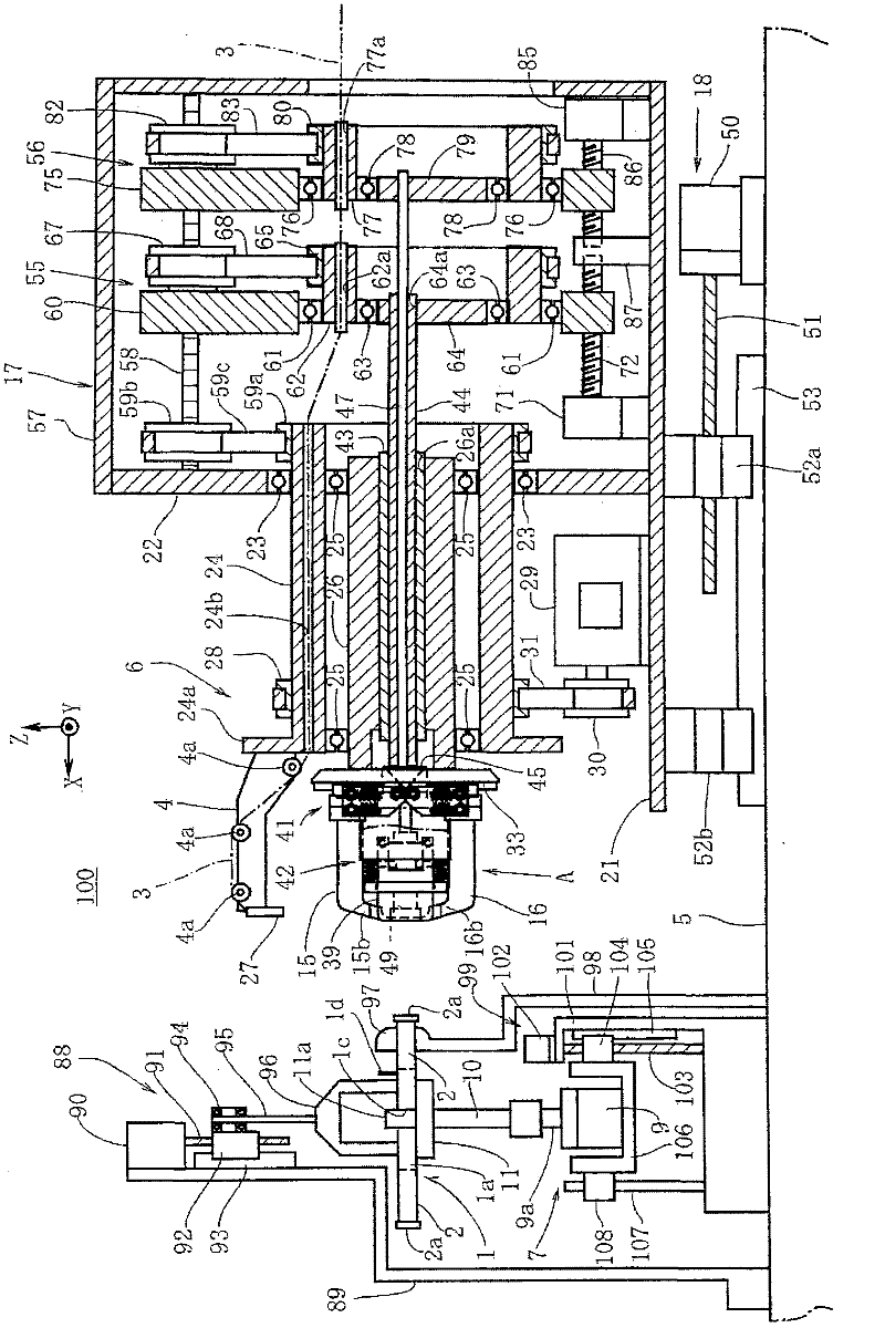
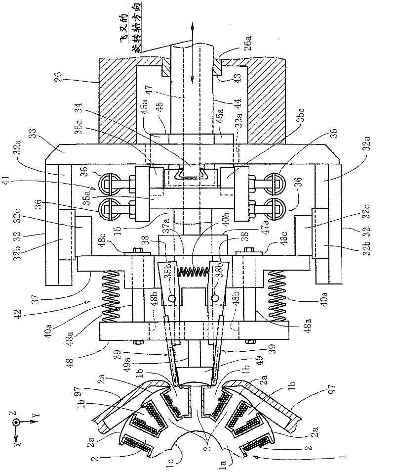
[0050] figure 1 Shown is the winding device 100 of the present invention. This winding device 100 is a device for winding a multilayer wire 3 around a plurality of magnetic poles 2 constituting a multi-pole armature 1 (stator) of a generator or a motor. Furthermore, this winding device 100 is a flyer-type winding device that performs winding using a flyer 4 that rotates around the magnetic pole 2 while drawing out the wire 3 . The multi-pole armature 1 in this embodiment is an armature including an annular portion 1a and 18 magnetic poles 2 protruding radially outward from the annular portion 1a ( image 3 Indicates 5 magnetic poles). like image 3 As shown, between the magnetic poles 2 in the multi-pole armature 1, a slot 1b is formed in the opening. The cross-section of the magnetic pole 2 is a quadrilateral, and the outer peripheral surface of the magnet...


PUM


Abstract

The invention provides a winding machine and a winding method. When the winding the performed on the first layer and the second layer, a top end of a side plate completely enters into the inner circumferential side of a magnetic pole and the wire is stably and regularly wound on the magnetic pole. The winding machine comprises: a flying fork capable of rotating around the magnetic pole of multi-pole armature and simultaneously leading out the wire and winding the wire relative to the magnetic pole; a pair of central winding molds configured to axially clamp the magnetic pole from the multi-pole armature and guide the wire led out from the flying fork to the magnetic pole; a pair of side plates configured to axially clamp the magnetic pole from the multi-pole armature and guide the wire led out from the flying fork to the magnetic pole. The pair of the side plates are configured to incline relative to a rotation shaft of the flying fork in the way of closing to the inner circumferential side of the multi-pole armature and change the inclined angle relative to the rotation shaft of the flying fork, therefore the top interval between the inner circumferential side of a magnetic pole and the side plate is changed.

Description

technical field [0001] The present invention mainly relates to a winding machine and a winding method for winding a wire for forming a coil on a multi-pole armature. Background technique [0002] Conventionally, in order to wind a wire for forming a coil on a magnetic pole of a multi-pole armature, a flyer-type winding machine having a flyer that draws out the wire while rotating around the magnetic pole and winds it around the magnetic pole has been widely used. wire. Moreover, in order to achieve better performance with the limited size of the armature such as a motor, it is required how the winding machine can perform more windings in the limited winding space of the multi-pole armature. In this regard, it is effective to wind adjacent wires neatly around the magnetic poles without gaps, that is, so-called neat winding. Therefore, the following flying fork type winding machine is known, comprising: a pair of central winding dies, which are configured to clamp the magnet...

Claims


Application Information

Patent Timeline
Patent Type & Authority Applications(China)
IPC IPC(8): H02K15/08
Inventor 福田滋
Owner NITTOKU ENG CO LTD
Why Eureka
Try Eureka