
System state control method and portable terminal

A system state, portable terminal technology, applied in the field of communication, can solve the problem of insufficiency of system state, and achieve the effect of improving consistency

Active Publication Date: 2014-11-05
LENOVO (BEIJING) LTD
View PDF2 Cites 0 Cited by
  • Summary
  • Abstract
  • Description
  • Claims
  • Application Information

AI Technical Summary

Problems solved by technology

[0004] The purpose of the embodiment of the present application is to provide a system state control method and a portable terminal to solve the problem in the prior art that when the master system and the slave system are combined or used separately, the system state cannot meet the user's actual use needs and automatically switch

Method used


Image

  • System state control method and portable terminal
  • System state control method and portable terminal
  • System state control method and portable terminal

Examples


no. 1 example

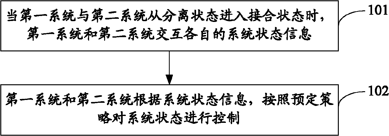
[0074] see figure 1 , the flow chart of the first embodiment of the system state control method of the present application:

[0075] Step 101: When the first system and the second system enter the engaged state from the separated state, the first system and the second system exchange respective system state information.

[0076] Step 102: the first system and the second system control the system status according to the system status information according to a predetermined policy.

[0077] Among them, the predetermined strategy may include: when the first system and the second system are in the same system state when they are in the separated state, after entering the engaged state, keep their respective system states unchanged, being in the same system state includes being in the working state at the same time, Or in the non-working state at the same time; when one of the first system and the second system is in the working state and the non-working state when they are in th...

no. 2 example

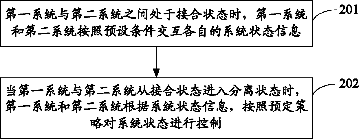
[0092] see figure 2 , the flow chart of the second embodiment of the system state control method of the present application:

[0093] Step 201: When the first system and the second system are in a joint state, the first system and the second system exchange respective system status information according to preset conditions.

[0094] When the first system and the second system are in the joint state, in order to ensure that the system state can be automatically controlled according to the original system state information after entering the separated state, the first system and the second system need to interact with their respective system states information. When exchanging system status information, it can be carried out according to preset conditions, including: the first system and the second system exchange their respective system status information according to a predetermined time interval; or, the first system and the second system exchange their respective system s...


PUM


Abstract

A system status control method and a portable terminal are described. The portable terminal includes a first system with a first interface and a second system with a second interface, and the first system and the second system are joined or separated through the first interface and the second interface. The method includes when the first system and the second system enter a joined-up status from a separated status, the first system and the second system exchanging respective system status information thereof; and the first system and the second system control the system status according to the system status information and based on a preset policy. When a master system and a slave system are combined or separated, automatic switch control may be performed on the system status according to a usage requirement of a user and based on the preset policy.

Description

technical field [0001] The present application relates to the technical field of communication, in particular to a system state control method and a portable terminal. Background technique [0002] A portable terminal with a mixed system architecture, where a mixed system refers to the combination of two or more systems. For example, on the basis of an existing system, at least another system (including another PC system or embedded system, etc.) Different systems can work together, share information and equipment, and give full play to their respective advantages. The existing common portable terminal with hybrid system architecture usually integrates a main system or first system (for example, Win7) and a slave system or second system (for example, Android), and the keyboard, keyboard, etc. can be shared between the main system and the slave system Network card, display screen, storage device, Audio (audio), etc., can be joined and separated on the mechanism and interface...

Claims


Application Information

Patent Timeline
Patent Type & Authority Patents(China)
IPC IPC(8): H04M1/725
CPCH04L29/00G06F13/14G06F9/4421G06F13/385G06F9/448
Inventor 景涛
Owner LENOVO (BEIJING) LTD
Learn More