Circuit structure for inhibiting on-off POP sound of audio power amplifier

A circuit structure and audio technology, applied in the direction of transducer acoustic response prevention, etc., can solve problems such as unsatisfactory effect and increased system cost

Inactive Publication Date: 2012-07-11
WUXI LINGHU TECH
View PDF5 Cites 7 Cited by
  • Summary
  • Abstract
  • Description
  • Claims
  • Application Information

AI Technical Summary

Problems solved by technology

[0003] At present, there are many solutions for suppressing POP sound. Some existing solutions are mostly to add some structures to suppress POP sound around the chip. This design obviously increases the system cost.
However, the traditional structure of suppressing POP sound inside the chip is not ideal.

Method used


Image

  • Circuit structure for inhibiting on-off POP sound of audio power amplifier
  • Circuit structure for inhibiting on-off POP sound of audio power amplifier
  • Circuit structure for inhibiting on-off POP sound of audio power amplifier

Examples


Embodiment Construction

[0014] The specific embodiments of the present invention will be further described below in conjunction with the accompanying drawings.

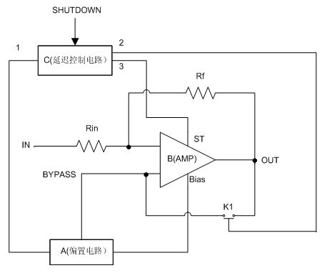
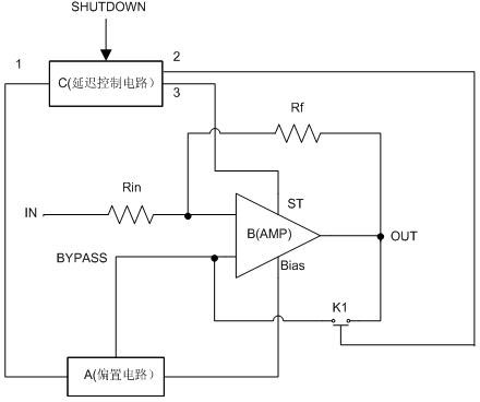
[0015] The circuit structure of the present invention is as figure 1 Shown: It is composed of bias circuit A, amplifier B, delay control circuit C, resistor Rin, resistor Rf and switch K1. The resistor Rin is connected to the positive input terminal of the amplifier B, the resistor Rf is connected in series between the positive input terminal and the output terminal of the amplifier B, and the switch K1 is connected in series between the negative input terminal BYPASS and the output terminal of the amplifier B; the bias circuit A is connected to the negative input terminal and the bias terminal of the amplifier B; the delay control circuit C is connected to the bias circuit A, the enable terminal of the amplifier AMPB and the switch K1.

[0016] Amplifier B, resistor Rin, and resistor Rf form a basic power amplifier unit. Bias circuit A pro...


PUM


Abstract

The invention discloses a circuit structure for inhibiting on-off POP sound of an audio power amplifier. The circuit structure comprises an amplifier, a bias circuit, a delay control circuit, a resistor Rin, a resistor Rf and a switch K1, wherein a basic power amplification unit is formed by the amplifier, the resistor Rin and the resistor Rf; the bias circuit supplies voltage reference and current reference to the amplifier; when an audio system is turned on or off, the delay control unit turns on or off the amplifier, the bias circuit and the switch according to different time sequences and time delays, so as to achieve the aim of inhibiting the POP sound produced when the system is turned on or off. By adopting the circuit structure, the POP sound produced when the audio system is turned on or off can be obviously inhibited, the impact to a horn is reduced and the auditory feeling of listeners can be improved.

Description

technical field [0001] The invention belongs to the hardware implementation of an integrated circuit (Integrated Circuit), and in particular relates to a circuit structure for suppressing the POP sound of an audio power amplifier switching on and off. Background technique [0002] POP sound refers to the transient impact caused by various operations when the audio device is powered on and off, and after the power is stabilized. An audio system usually includes components such as audio sources, power amplifiers, speakers, etc. If the various links are not properly designed, this kind of "POP" sound will be produced. Especially the power amplifier, if it is not properly protected, this "POP" sound impact may even burn the speaker, or reduce the quality of the speaker and shorten its life. Although the transient impact in the sound source system is not so harmful, after being amplified by the power amplifier, it is enough to impact the sound film of the speaker and the human e...

Claims


Application Information

Patent Timeline
Patent Type & Authority Applications(China)
IPC IPC(8): H04R3/02
Inventor 蒋毅强
Owner WUXI LINGHU TECH
Why Eureka
Try Eureka