Uplink power control method and device

A power control and power control module technology, applied in the field of communication, can solve the problem that the power control scheme is no longer applicable

Active Publication Date: 2012-07-11
DATANG MOBILE COMM EQUIP CO LTD
View PDF5 Cites 54 Cited by
  • Summary
  • Abstract
  • Description
  • Claims
  • Application Information

AI Technical Summary

Problems solved by technology

Therefore, the subframe-based power con

Method used


Image

  • Uplink power control method and device
  • Uplink power control method and device
  • Uplink power control method and device

Examples


Embodiment Construction

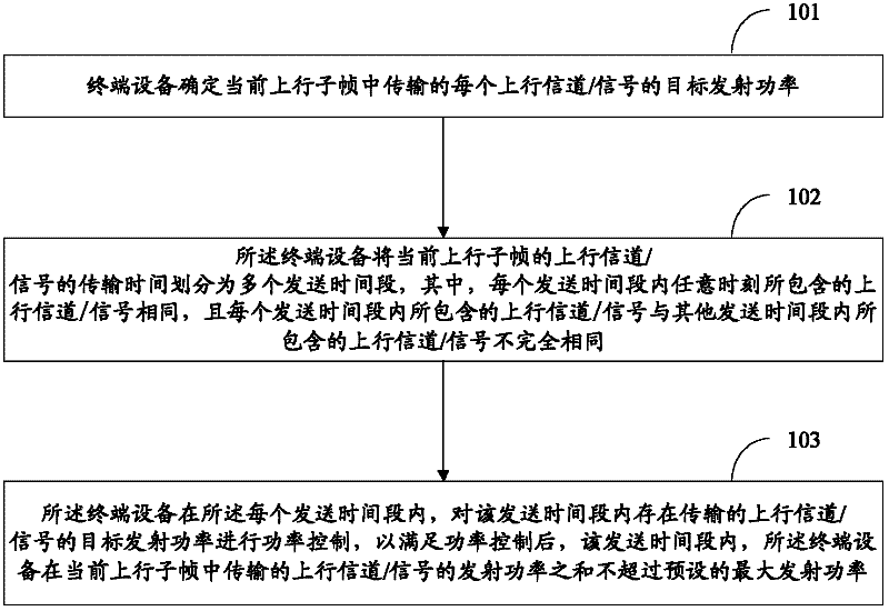
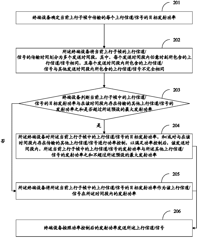
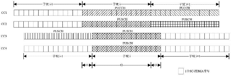
[0043] Since the transmission timing advances corresponding to the uplink channels / signals in one uplink subframe are different, the embodiment of the present invention divides the transmission time of the uplink channel / signal in one uplink subframe into multiple transmission time periods, and the transmission time The power control of each uplink channel / signal in the uplink subframe is carried out in units of segments, so that after the power control is satisfied, in each transmission time period, the transmission of the uplink channel / signal transmitted by the terminal device in the current uplink subframe The sum of the power does not exceed the preset maximum transmission power, which ensures that the system can work normally.

[0044] Preferably, the uplink sending times of the carriers belonging to the same TA group (group) are the same, that is, in the same uplink subframe, the sending times of the uplink channels on the carriers in the TA group are aligned.

[0045] ...


PUM


Abstract

The invention discloses an uplink power control method, which is used for realizing power control over uplink channels with different uplink transmission times so as to ensure that the total transmit power of terminal equipment in a sub-frame does not exceed maximum transmit power and that a system can normally work. The method comprises the following steps that: the terminal equipment determines the target transmit power of each uplink channel/signal transmitted in a current uplink sub-frame; the terminal equipment divides the transmission time of the uplink channels/signals in the current uplink sub-frame into a plurality of transmission time buckets, wherein the uplink channels/signals at any moment in each transmission time bucket are the same, and the uplink channels/signals in each transmission time bucket are incompletely the same as those in the other transmission time buckets; and in each transmission time bucket, the terminal equipment performs the power control on the target transmit power of the uplink channels/signals transmitted in the transmission time bucket to ensure that the transmit power sum of the uplink channels/signals transmitted in the transmission time bucket does not exceed the preset maximum transmit power of the terminal equipment after the power control. The invention also discloses a device for implementing the method.

Description

technical field [0001] The present invention relates to the communication field, in particular to an uplink power control method and device. Background technique [0002] In an LTE (Long Term Evolution, LTE long-term evolution) system, in order to ensure communication quality, one of the main means adopted is uplink power control. Through uplink power control, interference between user equipment (User Equipment, UE) that uses the same resource to send data in adjacent cells can be reduced as much as possible, and the transmission power of the UE can be ensured to be used reasonably. [0003] The uplink power that needs to be controlled mainly includes the transmit power of PUCCH (Physical Uplink Control Channel, physical uplink control channel), the transmit power of PUSCH (Physical Uplink Shared Channel, physical uplink shared channel), and SRS (Sounding Reference Signal, sounding reference signal) The transmit power of the channel and the transmit power of the PRACH (Phys...

Claims


Application Information

Patent Timeline
IPC IPC(8): H04W52/14
CPCH04L5/0007H04W56/005H04W52/14H04W52/34H04L5/001H04W52/246H04W52/367H04W52/281H04W52/325H04W52/146H04L5/0044H04L5/0053H04W56/0005H04W52/16H04W52/30
Inventor 高雪娟林亚男沈祖康潘学明
Owner DATANG MOBILE COMM EQUIP CO LTD
Why Eureka
Try Eureka