
Brake system and method for setting a braking torque of such a brake system

A technology of braking equipment and braking torque, applied in the direction of brakes, mechanical equipment, braking components, etc., can solve problems such as failure, increased wear of reducers, loss of comfort, etc., and achieve the effect of reducing deviation

Active Publication Date: 2012-07-11
VOITH PATENT GMBH
View PDF8 Cites 1 Cited by
  • Summary
  • Abstract
  • Description
  • Claims
  • Application Information

AI Technical Summary

Problems solved by technology

Such deviations can lead to a loss of comfort in the case of brake mixing, that is to say when the braking torques of the different braking systems of the vehicle, for example engine brake and hydrodynamic retarder, are superimposed in a targeted manner.
Especially if the available braking torque is less than desired, this is not satisfactory for the user of the brake system and may lead to complaints to the manufacturer
Conversely, an excessively high braking torque can be the cause of increased wear or even the failure of the retarder

Method used


Image

  • Brake system and method for setting a braking torque of such a brake system
  • Brake system and method for setting a braking torque of such a brake system
  • Brake system and method for setting a braking torque of such a brake system

Examples


Embodiment Construction

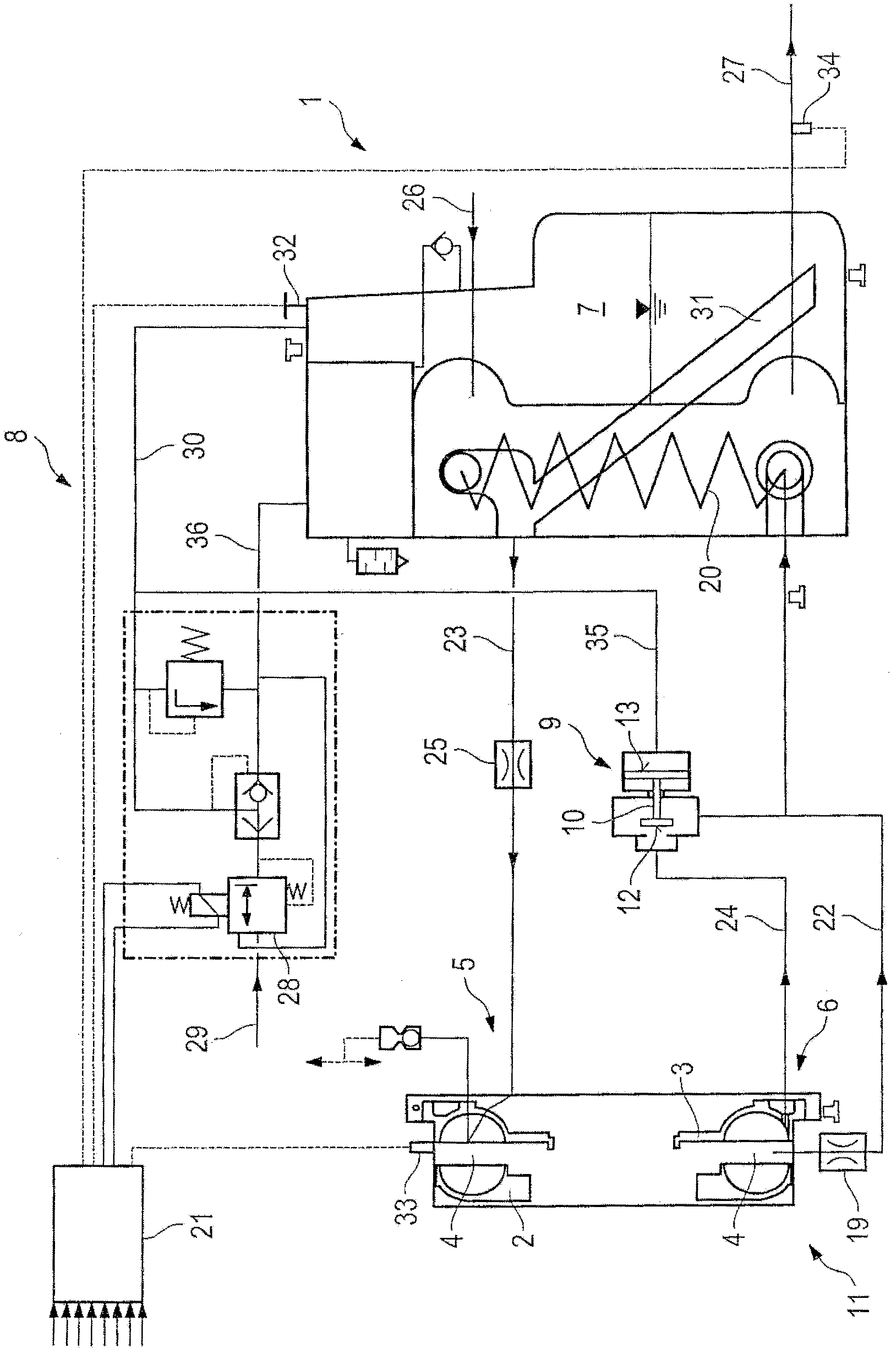
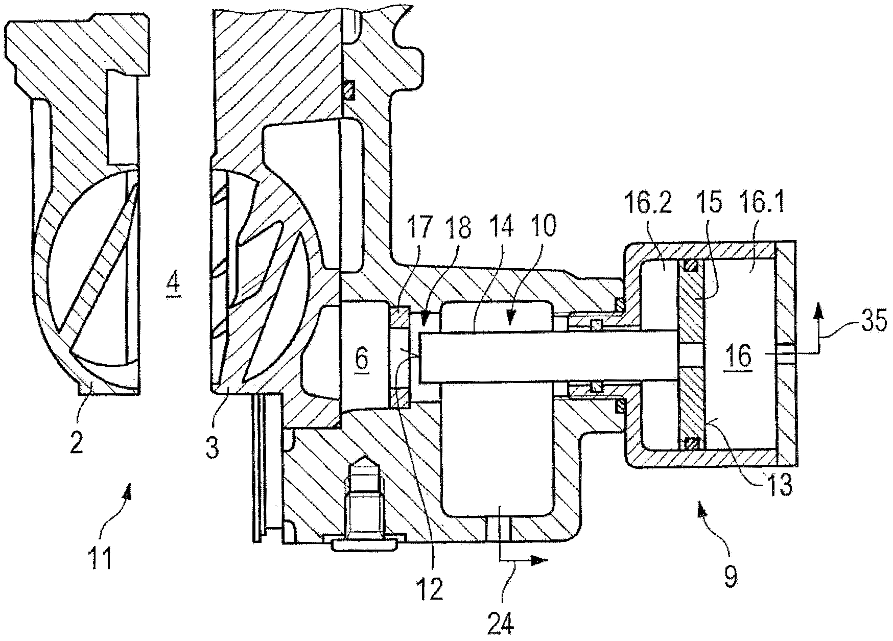
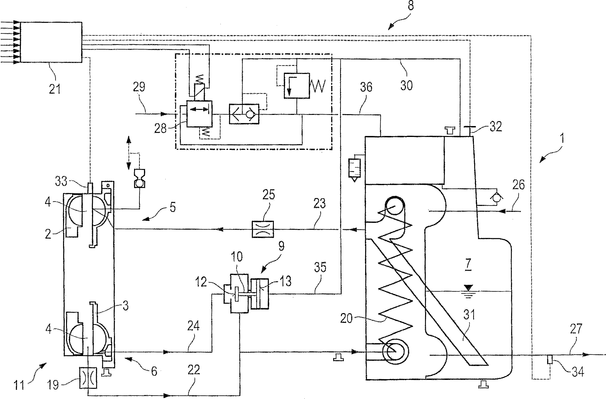
[0030] exist figure 1 shows a brake system of a vehicle with an external working medium circuit 1 conducting the working medium. In the working medium circuit 1, the following components are arranged one after the other in the flow direction: a hydraulic reducer 11, including a rotor 2 and a stator 3, and the rotor and the stator together form a torus-shaped working chamber 4; An opening of the connecting line 22 to the first working medium cooler 20 , wherein the working medium oil is also referred to as an oil cooler; a fixed restrictor 19 of constant cross-section arranged in the first connecting line 22 ; A working medium cooler 20 ; an opening of a second connecting line 23 from the working medium cooler 20 to the working chamber 4 of the hydrodynamic retarder 11 ; and a further throttle 25 . Here, the second connecting line 23 opens into the inlet 5 , through which the working chamber 4 can be filled with working medium from the first connecting line 23 of the external ...


PUM


Abstract

The invention relates to a brake system, in particular for a motor vehicle, comprising an external working-medium circuit and a hydrodynamic retarder that includes a bladed rotor and a bladed stator, which together form a toroidal working chamber, which can be filled with working medium from the external working-medium circuit through an inlet, wherein said working medium is conducted back into the external working-medium circuit through an outlet. The brake system further comprises a storage chamber for accommodating working medium that is currently not located in the working chamber or circulating in the external working-medium circuit and comprises a pressurization system for applying a control pressure to the working medium contained in the storage chamber so that more or less working medium is forced into the working chamber in order to set a desired braking torque. The invention is characterized by a throttle valve connected downstream of the outlet and including a movable or deformable valve body in order to vary the flow cross-section for working medium from the working chamber, wherein the valve body is exposed to working-medium pressure from the working chamber of the hydrodynamic retarder in the opening direction of the throttle valve and to the control pressure or a pressure dependent on the control pressure in the closing direction.

Description

technical field [0001] The invention relates to: a brake system with a hydrodynamic retarder, as it is used for continuous braking in motor vehicles, such as buses, trucks or rail vehicles; The method of braking torque of the braking device of the reducer. Background technique [0002] The hydrodynamic retarder has a working chamber which is filled with a working medium for the hydraulic transmission of torque from the driven primary impeller (rotor) to the fixed secondary impeller, which is therefore also called the stator. Instead of a fixed secondary impeller, it is also possible to provide a secondary impeller that rotates counter to the direction of rotation of the primary impeller, in order to form a counter-rotating reducer. The working medium in the rotor is accelerated radially outwards by driving the rotor by means of a shaft to be braked, for example a gearbox output shaft or indirectly a shaft (cardan shaft) which is connected in a non-rotational manner to the d...

Claims


Application Information

Patent Timeline
Patent Type & Authority Applications(China)
IPC IPC(8): B60T1/087B60T10/02F16D57/00F16D57/06
CPCB60T1/087F16D57/02B60T10/02F16D57/00
Inventor 迪特尔・劳克曼
Owner VOITH PATENT GMBH
Learn More