Vehicle body structure

A body and structure technology, applied in the direction of upper structure, vehicle parts, upper structure sub-assembly, etc., can solve the problem of weight increase of the body 200

Active Publication Date: 2012-07-11
HONDA MOTOR CO LTD
View PDF5 Cites 41 Cited by
  • Summary
  • Abstract
  • Description
  • Claims
  • Application Information

AI Technical Summary

Problems solved by technology

In addition, if only the left and right floor frames 202, 202 are reinforced, the weight of the vehicle body 200 will increase, so it is not a preferable measure.

Method used


Image

  • Vehicle body structure
  • Vehicle body structure
  • Vehicle body structure

Examples


Embodiment 1

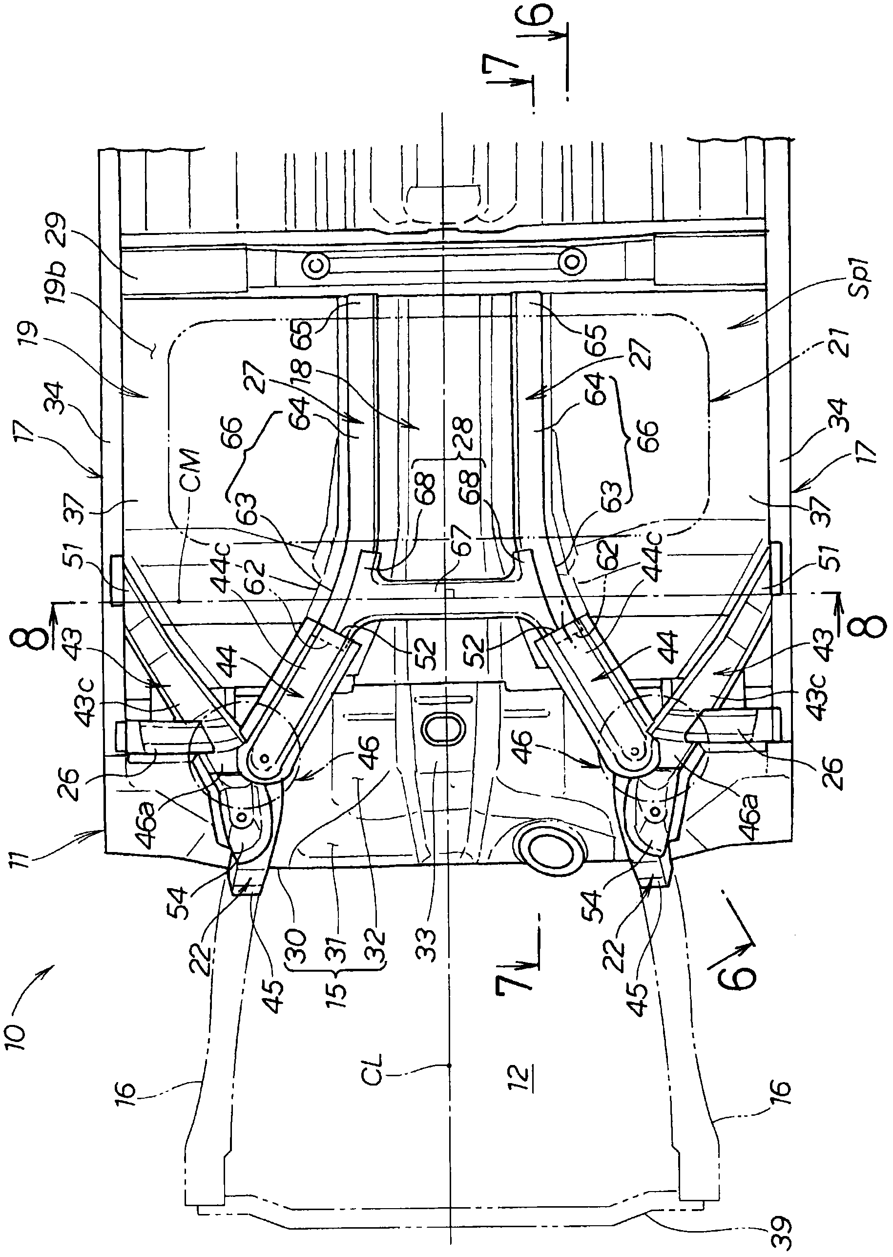
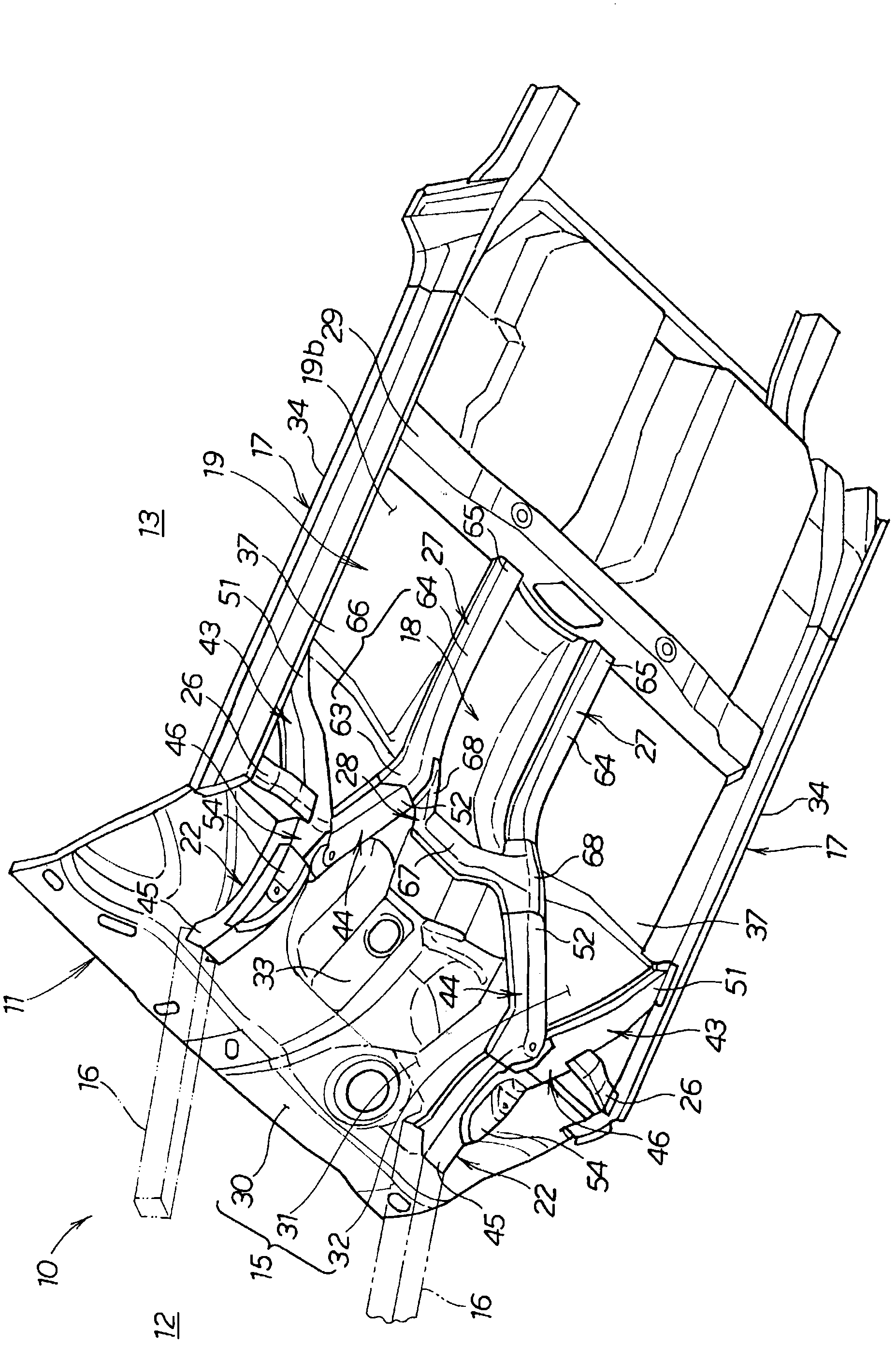
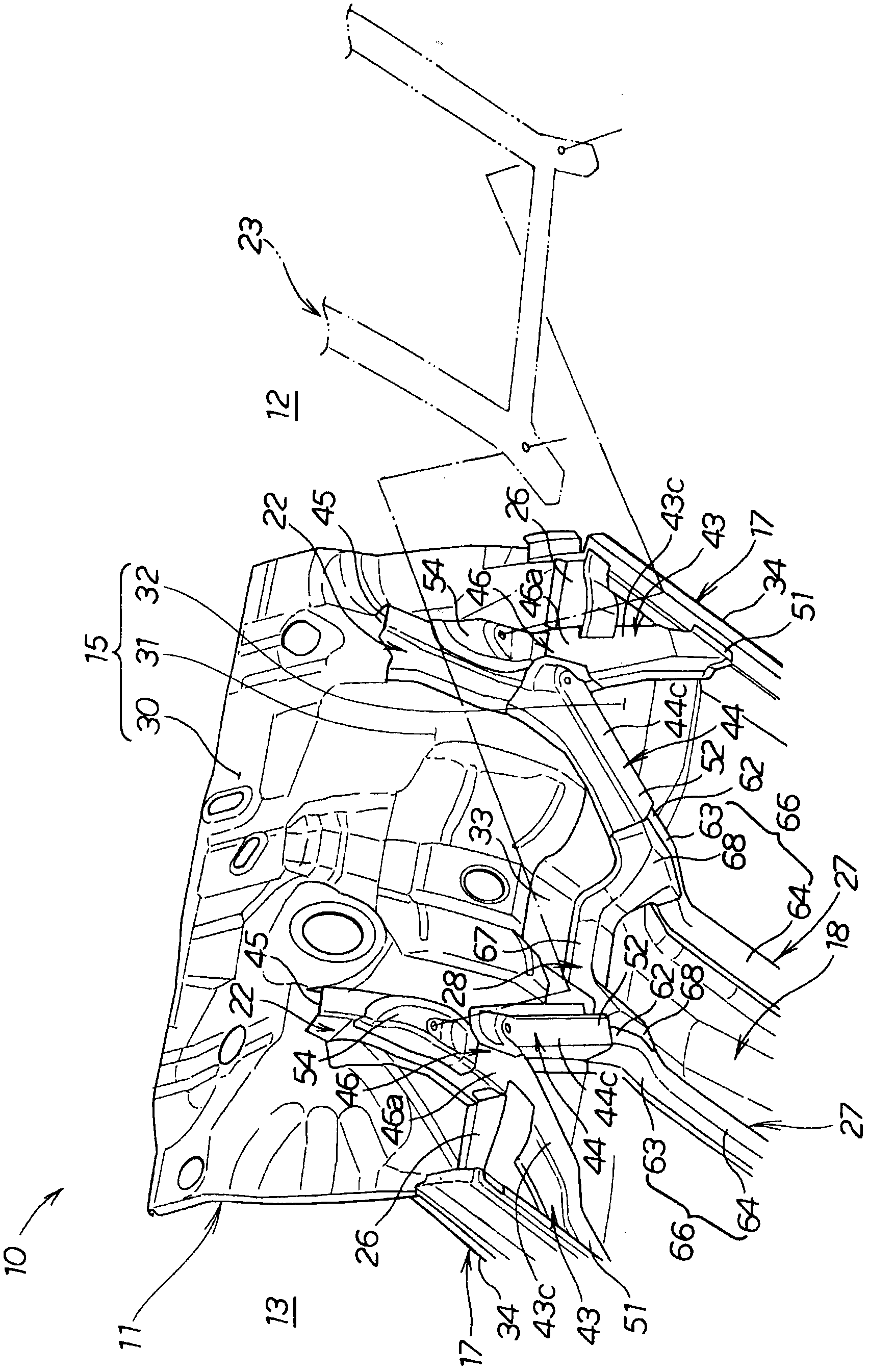
[0114] Regarding the vehicle body structure of Embodiment 1, according to Figure 1 to Figure 11 Be explained. like figure 1 and figure 2 As shown, the vehicle 10 of Embodiment 1 is a passenger car, and an engine compartment 12 at the front and a vehicle compartment 13 located directly behind the engine compartment 12 are formed inside a vehicle body 11 . This vehicle 10 is equipped with a fuel tank 21 on the front half of the vehicle body 11 .

[0115]The vehicle body 11 is constituted by a monorail body, and is formed in a bilaterally symmetrical shape with respect to a vehicle width centerline CL extending in the vehicle front-rear direction passing through the vehicle width center of the vehicle 10 . The front half of the vehicle body 11 includes: an instrument panel 15; left and right front side frames 16, 16; left and right side members 17, 17; a tunnel portion 18; The connecting parts 26,26 of the left and right sides; The channel frame 27,27 of left and right sid...

Embodiment 2

[0177] Regarding the vehicle body structure of Embodiment 2, according to Figure 12 and Figure 13 Be explained. Figure 12 The vehicle body 11 of the vehicle 10A of the illustrated embodiment 2 is characterized in that the figure 1 In the vehicle body 11 of the vehicle 10 shown in Embodiment 1, left and right front beams 73 and 73 are added, and other structures are the same as those described above. Figure 1 to Figure 11 The shown configurations are substantially the same, so the same reference numerals are used, and explanations thereof are omitted.

[0178] like Figure 12 As shown, the left and right front beams 73 , 73 extend on the beam extension line CM in the vehicle width direction, and are overlapped and joined to the upper surface 19 a of the floor panel 19 . The inner ends in the vehicle width direction of the left and right front cross members 73 are located on the main body portion 67 of the tunnel cross member 28 and on the left and right front curved po...

Embodiment 3

[0190] Regarding the vehicle body structure of Embodiment 3, according to Figure 14 to Figure 16 Be explained. Figure 14 and Figure 15 The vehicle body 11 of the vehicle 10B of the illustrated embodiment 3 is characterized in that, with respect to Figure 12 The body 11 of the shown embodiment 2 has changed the following two aspects, and regarding other structures, due to the above-mentioned Figure 1 to Figure 13 The shown configurations are substantially the same, so the same reference numerals are assigned and explanations are omitted. The first point of change is that the positions of the left and right front beams 73 and 73 are changed. The second point of change is that the mounting position of the fuel tank 21 (energy container 21 ) is changed.

[0191] like Figure 14 and Figure 15 As shown, the left and right front beams 73 , 73 of the third embodiment are located behind the tunnel beam 28 . A connecting beam 75 is bridged between the left side and the righ...


PUM


Abstract

A vehicle body (11) including: a tunnel cross-member (28) extending in the vehicle's widthwise direction along the lower surface of a tunnel section (18) of the floor panel (19); left and right side-frame extensions (22, 22) extending rearward along the lower surfaces (31, 32) of the dashboard (15) from the rear ends of left and right front side-frames (16, 16). The left and right side-frame extensions each bifurcate into a side sill-side extension (43, 43) which, while tilting, extends rearward and outward in the vehicle's widthwise direction from the rear end of each of the left and right side-frame extensions to a side sill (17, 17), and into a tunnel-side extension (44, 44) which, while tilting, extends rearward and inward in the vehicle's widthwise direction from the rear end of each of the left and right side-frame extensions to the tunnel cross-member. The tilt of the side sill-side extensions and the tilt of the tunnel-side extensions are substantially the same.

Description

technical field [0001] The present invention relates to the structure of a vehicle body in a vehicle such as a passenger car, and in particular relates to the ability to arrange energy containers for storing various energy sources, such as fuel tanks, batteries, or fuel cells, under the driver's seat and under or on the front floor body, or a body that can be arranged behind the driver's seat. Background technique [0002] Document 1 discloses a vehicle body in which a fuel tank is arranged under a driver's seat and under a front floor. Regarding the outline of the front part of the vehicle body disclosed in Reference Document 1, according to Figure 56 Be explained. Figure 56 The plan view structure of the front part of the vehicle body disclosed by patent document 1 is shown schematically. [0003] like Figure 56 As shown, in the front part of the vehicle body 200, the left and right floor frames 202, 202 extend rearward from the rear ends of the left and right front si...

Claims


Application Information

Patent Timeline
Patent Type & Authority Applications(China)
IPC IPC(8): B62D25/20
CPCB62D25/025B62D25/2018B62D25/2036
Inventor 石园学露崎匠友泽幸作
Owner HONDA MOTOR CO LTD
Why Eureka
Try Eureka