Fuel flowmeter having an improved control device

A technology of fuel flow and flow meter, which is applied in the fuel valve of turbine/propulsion device, fuel control of turbine/propulsion device, jet propulsion device, etc., and can solve problems such as engine speed increase

Active Publication Date: 2012-07-11
TURBOMECA SA
View PDF6 Cites 10 Cited by
  • Summary
  • Abstract
  • Description
  • Claims
  • Application Information

AI Technical Summary

Problems solved by technology

This causes circuit 22 to close and results in a significant undesired increase in the rate at which fuel is supplied to the engine

Method used


Image

  • Fuel flowmeter having an improved control device
  • Fuel flowmeter having an improved control device
  • Fuel flowmeter having an improved control device

Examples


Embodiment Construction

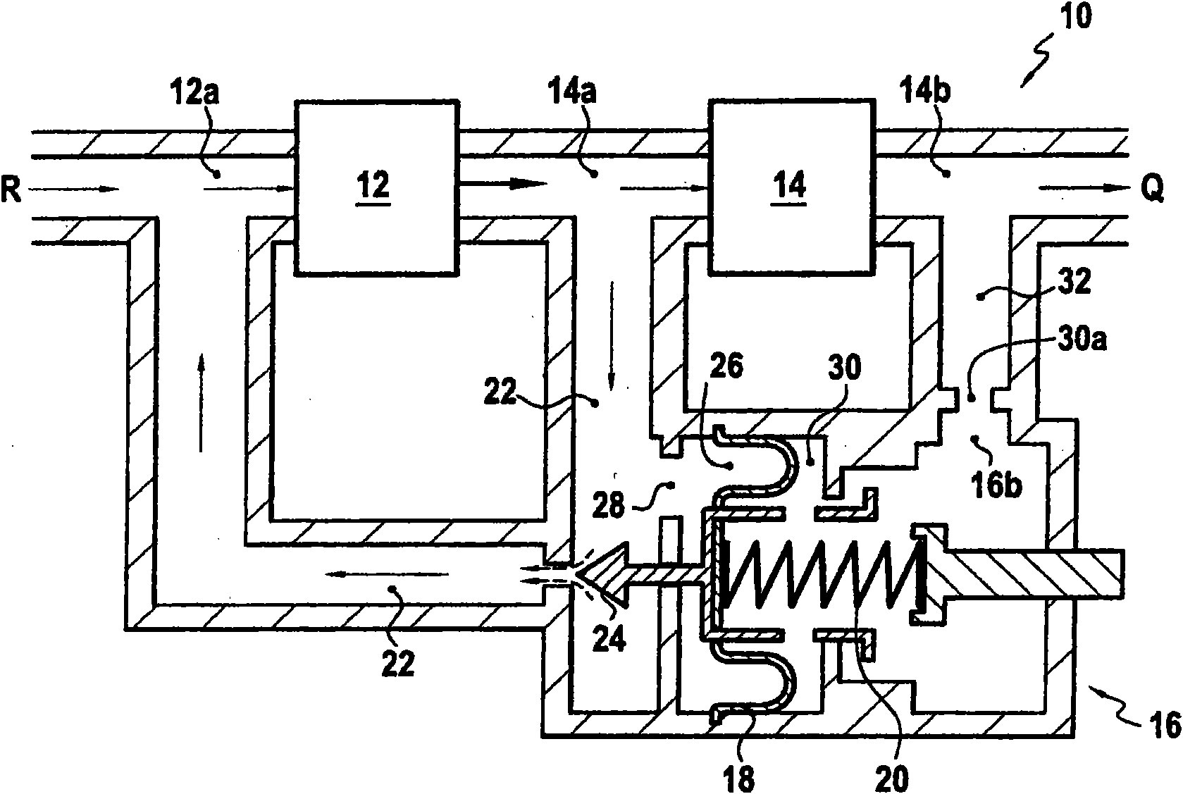
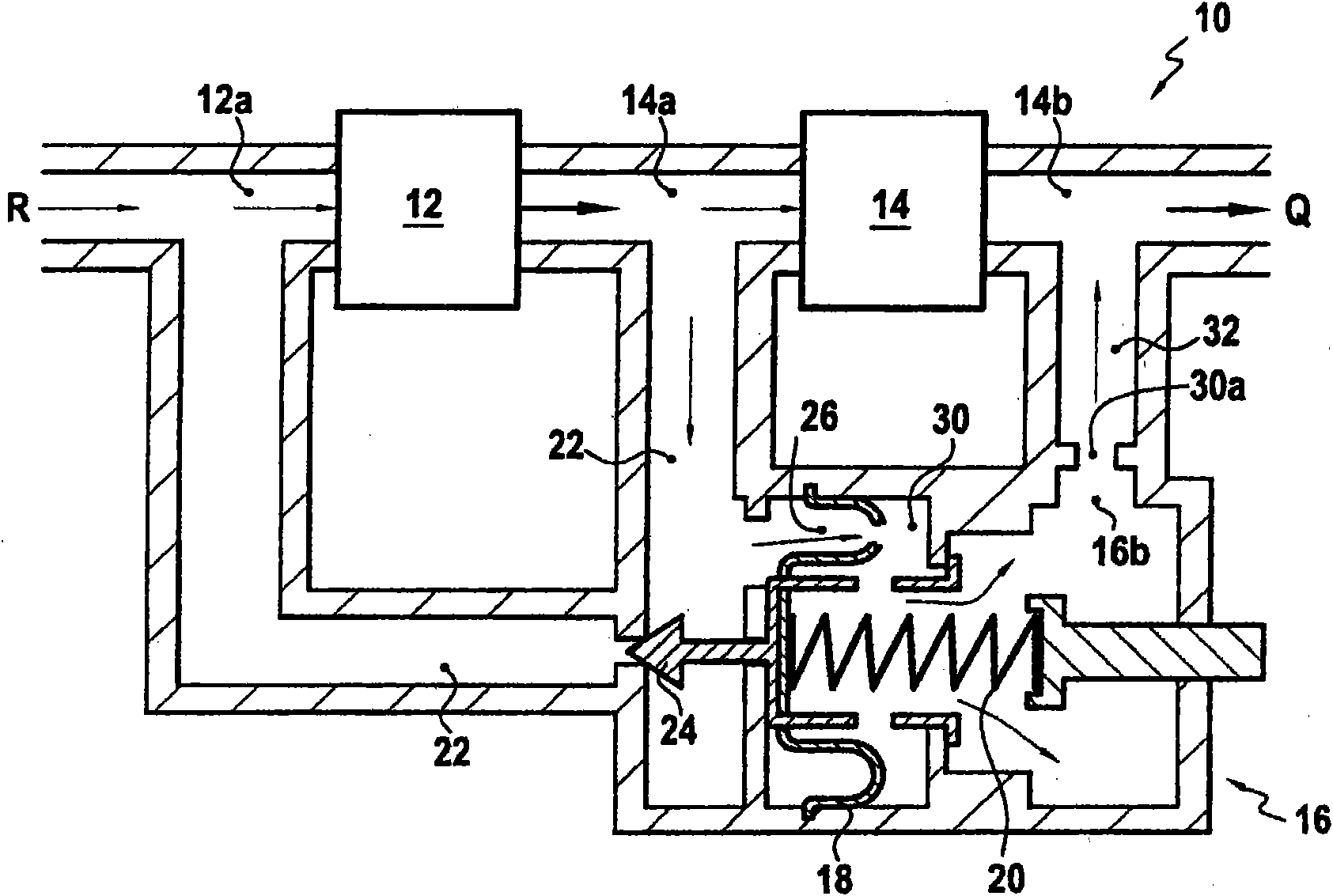
[0041] Figure 1, which shows a prior art fuel flow meter, has been described in the background section of the above specification. It should be noted that the pump is connected to the fuel tank R, and the regulator device 16 has a first chamber 26 in communication with the circuit 22 . This communication is preferably through an opening 28 formed upstream of the valve member 24 .

[0042] In normal operation, this first chamber is delimited in particular by a detection surface 18 , in particular a flexible diaphragm, such that the pressure in the first chamber is equal to the pressure at the inlet 14a of the metering valve 14 .

[0043] The prior art regulator device also includes a second chamber defined by the partition 18 and communicating with an outlet circuit 32 connecting the outlet 16b of the regulator device with the outlet 14b of the metering valve 14 . It can therefore be understood that the fuel pressure in the second chamber is equal to the pressure at the outlet...


PUM


Abstract

A fuel flowmeter (110) for being fed by a pump (112) including an inlet (112a) and an outlet (112b), including: a metering valve (114) including an inlet (114a) and an outlet (114b), and arranged downstream from the outlet of the pump; a delivery circuit (122) connecting the inlet of the metering valve to the inlet of the pump; and a pressure control device (116) comprising a movable flap capable of closing and opening the delivery circuit, wherein a differential pressure detection surface (118) attached to the flap (124) axially defines a first chamber (126) in communication with the delivery circuit and a second chamber (130) in communication with the metering valve outlet, a piston (150) axially defining the second chamber (130) of a third chamber (152) connected to the metering valve outlet, said piston comprising a coupling member (170) capable of engaging with the flap. A second spring (164), provided in the third chamber, maintains the piston uncoupled from the flap. In addition, the control device comprises a channel (154) connecting the second chamber (130) to the third chamber (152).

Description

technical field [0001] The invention relates to the field of regulating the supply of fuel passing through an engine such as an aircraft turbine engine. [0002] More specifically, the present invention relates to a flow meter for fuel supplied by a pump having an inlet and an outlet, said flow meter comprising: [0003] - a metering valve with an inlet and an outlet, said valve being arranged downstream of the outlet of said pump; [0004] a circuit connecting the inlet of the metering valve to the inlet of the pump; and [0005] a pressure regulating device comprising: a movable valve member adapted to close and open said circuit; a differential pressure detection surface fastened to said valve member, and axially separate a first chamber from a second chamber, wherein the first chamber communicates with the inlet of the metering valve, and the second chamber communicates with the outlet of the metering valve; a first spring, the A first spring is arranged on said second ...

Claims


Application Information

Patent Timeline
Patent Type & Authority Applications(China)
IPC IPC(8): F02C7/232F02C9/26
CPCF05D2270/3015F05B2270/3015F02C7/232F02C9/263Y10T137/7773
Inventor 飞利浦・吉恩・雷内・玛丽・本尼扎克布鲁诺・法卡卢多维克・亚历山大・里格里斯塞德里克・罗杰・佐丹
Owner TURBOMECA SA
Why Eureka
Try Eureka