Method and device for determining upperband signal from narrowband signal

A narrow-band, up-frequency technology, applied in the field of communication systems, can solve problems such as poor voice quality at the receiver

Inactive Publication Date: 2014-02-12
QUALCOMM INC
View PDF4 Cites 2 Cited by
  • Summary
  • Abstract
  • Description
  • Claims
  • Application Information

AI Technical Summary

Problems solved by technology

This allows more users to access the network, but also results in poor voice quality at the receiver

Method used


Image

  • Method and device for determining upperband signal from narrowband signal
  • Method and device for determining upperband signal from narrowband signal
  • Method and device for determining upperband signal from narrowband signal

Examples


Embodiment Construction

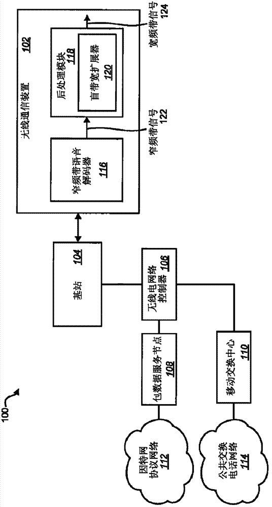
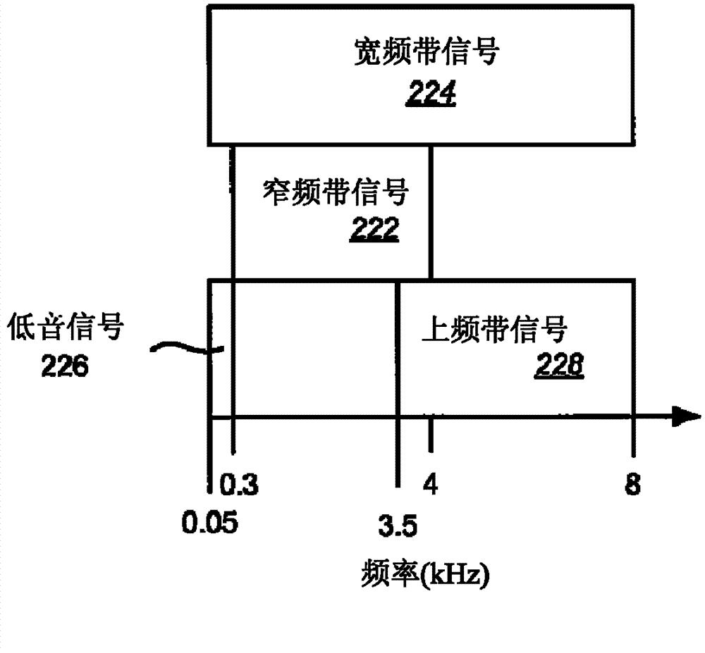
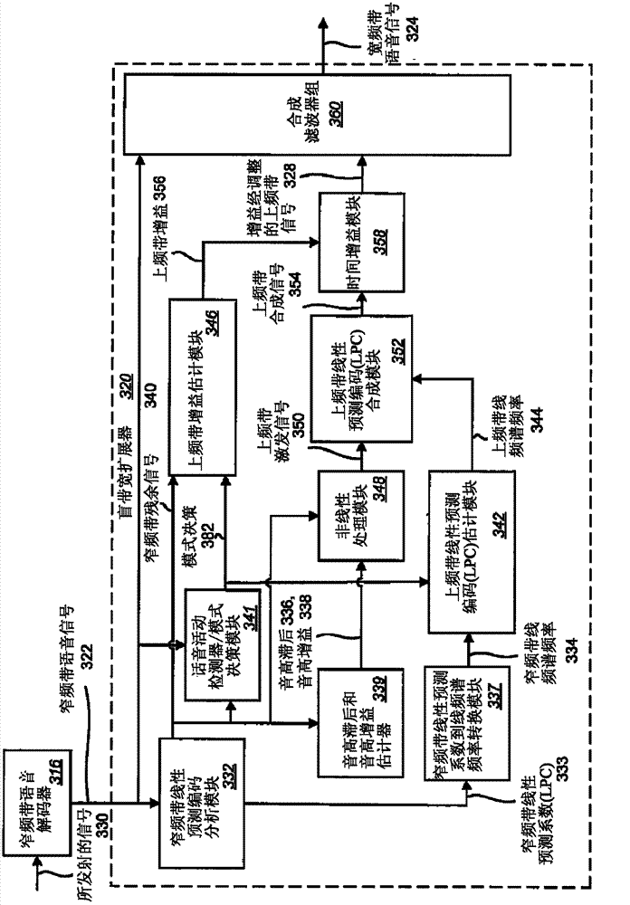
[0026] Listening to wideband speech (50Hz to 8000Hz) is desirable (as opposed to narrowband speech) because it is of higher quality and generally sounds better. In many cases, however, only narrowband voice is available because voice communications via traditional landline and wireless telephone systems are often limited to a narrowband frequency range of 300 Hz to 4000 Hz. Wideband voice transmission and reception systems are becoming more popular, but will require major changes to existing infrastructure, which will take considerable time. Meanwhile, blind bandwidth extension techniques are being used which act as a post-processing module acting on the received narrowband speech to extend the bandwidth of the narrowband speech to the wideband frequency range without any side information from the encoder. The blind estimation algorithm estimates the upper frequency band (3500 Hz to 8000 Hz frequency band) and lower frequency (50 Hz to 300 Hz) content entirely from the narrowb...


PUM


Abstract

A method for determining an upperband speech signal from a narrowband speech signal is disclosed. A list of narrowband line spectral frequencies (LSFs) is determined from the narrowband speech signal. A first pair of adjacent narrowband LSFs that have a lower difference between them than every other pair of adjacent narrowband LSFs in the list is determined. A first feature that is a mean of the first pair of adjacent narrowband LSFs is determined. Upperband LSFs are determined based on at least the first feature using codebook mapping.

Description

[0001] Related applications [0002] This application is related to and claims priority to U.S. Provisional Patent Application No. 61 / 254,623, filed October 23, 2009, entitled "Determining an Upperband Signal from a Narrowband Signal" . technical field [0003] The present invention generally relates to communication systems. More specifically, the present invention relates to determining an upper-band signal from a narrow-band signal. Background technique [0004] Wireless communication systems have become an important means by which many people around the world communicate. A wireless communication system may provide communication for many wireless communication devices, each of which may be served by a base station. A wireless communication device is capable of using multiple protocols and operating at multiple frequencies to communicate in multiple wireless communication systems. [0005] In order to accommodate many users, different techniques are used to maximize ...

Claims


Application Information

Patent Timeline
Patent Type & Authority Patents(China)
IPC IPC(8): G10L21/038
CPCG10L21/038G10L21/02G10L19/08
Inventor 文卡特什·克里希南丹尼尔·J·辛德尔阿南塔帕德玛纳班·阿拉桑尼帕莱·坎迪哈代
Owner QUALCOMM INC
Why Eureka
Try Eureka