
A pulse condition collection contact device

A technology of pulse condition and bionic hand, applied in catheters and other directions, can solve problems such as poor compliance, complex structure, and impact on implementation effects, and achieve the effects of improving reliability and service life, reducing energy loss, and strong adaptability

Inactive Publication Date: 2014-10-01
HENAN NEPTUNE TECH DEV CO LTD
View PDF7 Cites 1 Cited by
  • Summary
  • Abstract
  • Description
  • Claims
  • Application Information

AI Technical Summary

Problems solved by technology

Traditional pulse diagnosis contacts are composed of rigid vertical pressure sensors, such as the utility model patent and publication number CN102258367A of the three-part pulse signal acquisition and analyzer with the publication number CN201624647U and the name of Cun, Guan and Chi. The patent application for the invention of the pulse-sensing instrument all adopts a purely mechanical structure, using motors or hydraulics to drive the mechanical parts to move up, down, left, and right. The disadvantage is that the structure is complex, the flexibility is poor, and it can only move in a straight line, which is inconsistent with traditional Chinese medicine fingers. Cannot actively adapt to the shape of the patient's wrist, which affects the implementation effect
There are also some further improved pulse diagnosis manipulators that use a three-segment connection structure, which increases the flexibility of the fingers and can complete more complex movements, such as the bending of the fingers. However, because it is still a mechanical structure in essence, it is not as flexible as the human fingers. same, it is difficult to guarantee the authenticity of the pulse signal collected

Method used


Image

  • A pulse condition collection contact device
  • A pulse condition collection contact device
  • A pulse condition collection contact device

Examples


Embodiment Construction

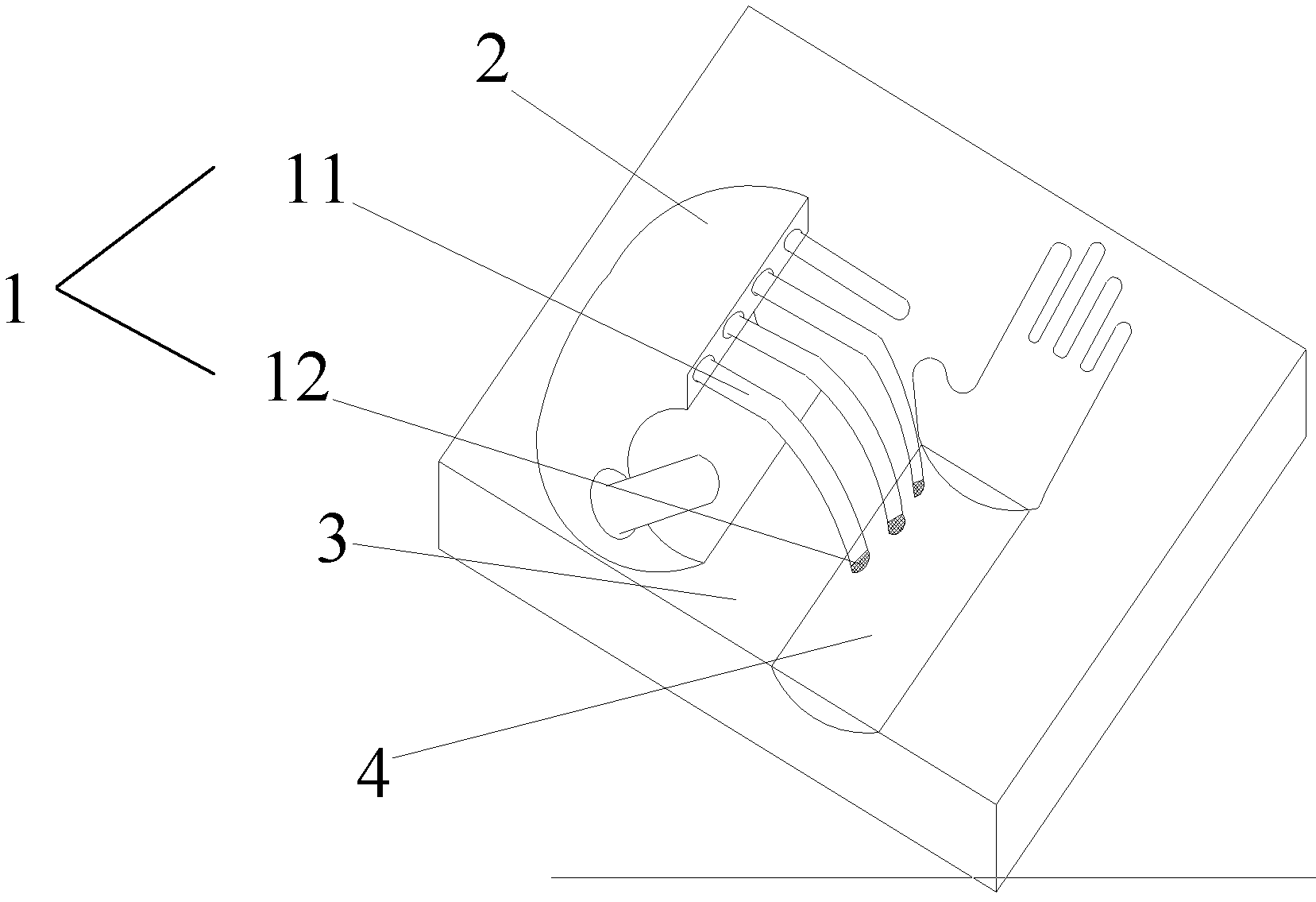
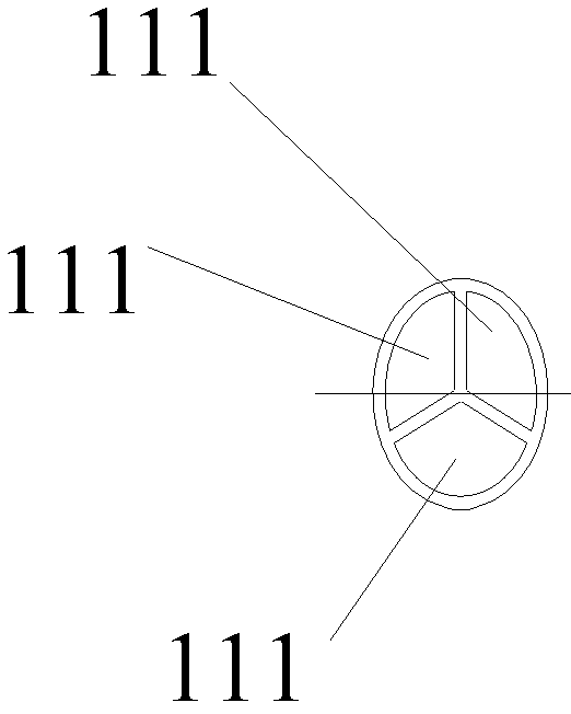
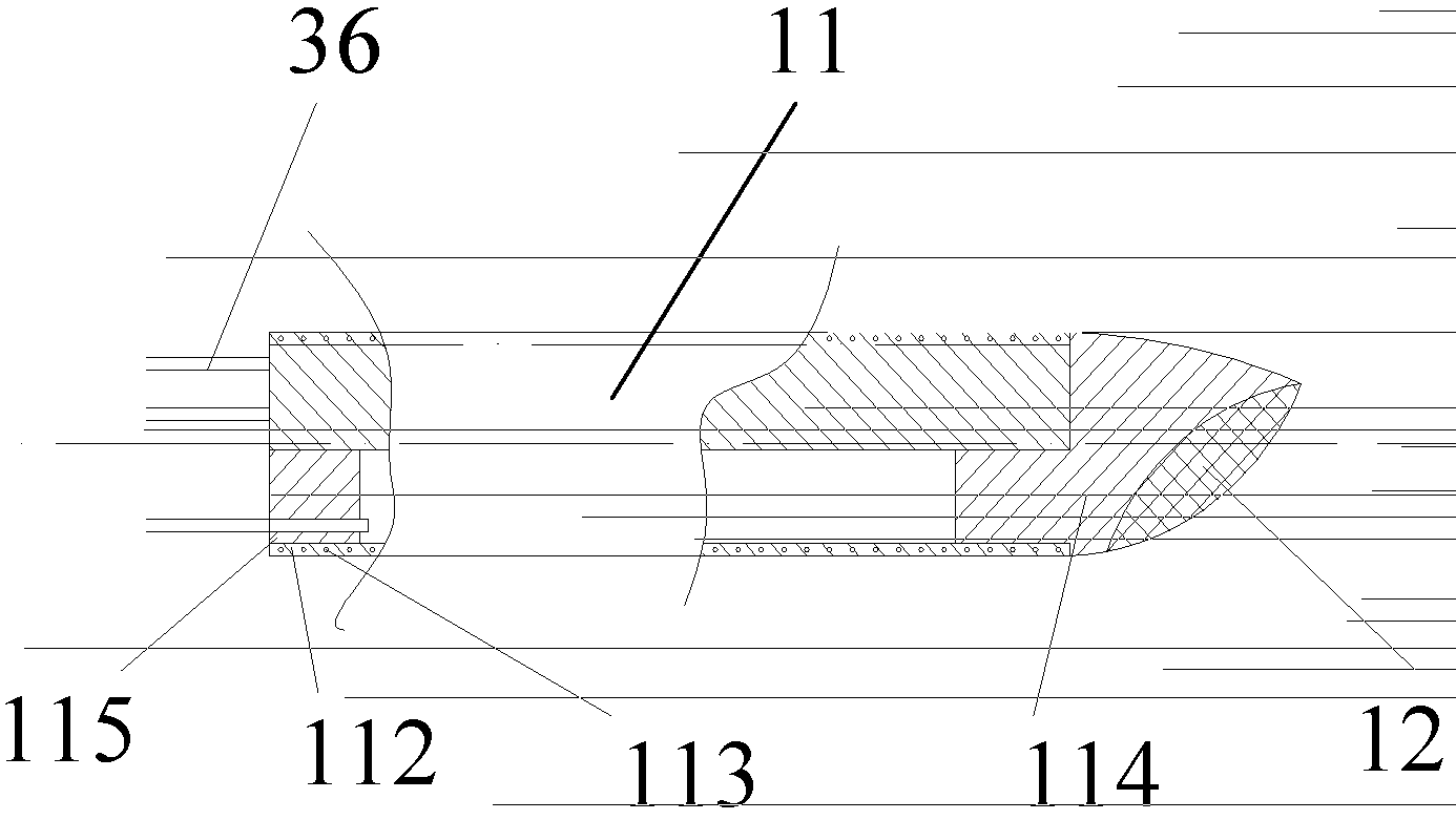
[0026] The structure of the pulse condition collection contact device described in one embodiment of the present invention is as follows: figure 1 shown. The pulse acquisition contact device includes a bionic hand 1, a bionic hand support 2 supporting the bionic hand 1, and a pulse diagnosis platform 3 for fixing the bionic hand support 2 and the patient's arm. Wherein, the bionic hand 1 includes a flexible finger 11 and an array pressure sensor 12 located at the front end of the flexible finger 11. The bionic hand 1 preferably includes three flexible fingers 11, and the three flexible fingers 11 are horizontally arranged and installed on the bionic hand support 2. The inner cavity of each flexible finger 11 is divided into a plurality of air chambers along the circumference, and each air path of the pneumatic system communicated with each air chamber controls the pressure of the air chambers in the flexible finger 11 . The array pressure sensor 12 is connected to the control...


PUM


Abstract

The invention discloses a pulse condition acquiring contact device, which comprises a bionic hand (1), a bionic hand support (2) and a pulse-taking platform (3). The bionic hand support (2) supports the bionic hand (1), and the bionic hand support (2) and an arm of a patient are fixed on the pulse-taking platform (3). The bionic hand (1) comprises flexible fingers (11) and array type pressure sensors (12) located at front ends of the flexible fingers (11). An inner cavity of each flexible finger (11) is divided into a plurality of air chambers along the periphery of the flexible finger (11), and the air chambers are communicated with various air channels of a pneumatic system. The array type pressure sensors (12) are connected onto a control system, and the control system drives air with certain pressure to be injected into the air chambers from the air channels of the pneumatic system according to pulse pressure information received from the array type sensors (12). The flexible fingers are designed integrally, hinge among joints is omitted, the fingers are controlled to move by high pressure air, energy loss in a pneumatic process is reduced, reliability is improved, and the service life of the flexible fingers is prolonged. Simultaneously, a three-cavity structure is adopted, so that movement with multiple degrees of freedom can be realized.

Description

technical field [0001] The invention relates to a medical device based on the theory of traditional Chinese medicine, in particular to a pulse condition collection contact device. Background technique [0002] The pulse diagnosis test contact device is an important part in the design of the traditional Chinese medicine pulse diagnosis system, and it is also a key difficulty. The performance of the pulse diagnosis contact part directly determines the accuracy and reliability of the pulse diagnosis. Traditional pulse diagnosis contacts are composed of rigid vertical pressure sensors, such as the utility model patent and publication number CN102258367A of the three-part pulse signal acquisition and analyzer with the publication number CN201624647U and the name of Cun, Guan and Chi. The patent application for the invention of the pulse-sensing instrument all adopts a purely mechanical structure, using motors or hydraulics to drive the mechanical parts to move up, down, left, and...

Claims


Application Information

Patent Timeline
Patent Type & Authority Patents(China)
IPC IPC(8): A61B5/02
Inventor 许若锋王常海田瑞曼崔利宏张涛齐永奇李寒冰赵玉君
Owner HENAN NEPTUNE TECH DEV CO LTD
Learn More