Automatic grinding and polishing system of crystal blank

A technology for blanks and crystals, applied in the field of automatic grinding and polishing systems for crystal blanks, can solve the problems of difficult mechanism layout, high requirements on machine manufacturing precision, difficult manufacturing and transportation, etc., so as to reduce machine energy consumption and material manufacturing costs, The effect of simplifying the transfer and circulation mode of the fixture and simplifying the complexity of the mechanism action

Active Publication Date: 2014-07-30
虞雅仙
View PDF17 Cites 0 Cited by
  • Summary
  • Abstract
  • Description
  • Claims
  • Application Information

AI Technical Summary

Problems solved by technology

During the actual implementation of this technical solution, the inventor found the following problems: First, at the docking station, the two docking fixtures are respectively located on the two rotating frames, which requires high manufacturing precision and is difficult Ensure the docking accuracy; secondly, the machine is large in size, which is difficult to manufacture and transport; thirdly, the space for the docking station, loading station, and unloading station is limited, and the complex structure design and cumbersome actions affect the processing efficiency
However, all the stations of the whole machine are arranged around a cantilever turntable (equivalent to a rotating frame), the machine is huge in size, difficult to manufacture and transport, the space of each station is small, the mechanism layout is difficult, and it is inconvenient for equipment installation and maintenance; its grinding and polishing The station uses a manipulator to transfer the fixture, which also has problems such as difficult manufacturing and high manufacturing precision requirements.

Method used


Image

  • Automatic grinding and polishing system of crystal blank
  • Automatic grinding and polishing system of crystal blank
  • Automatic grinding and polishing system of crystal blank

Examples


Embodiment 1

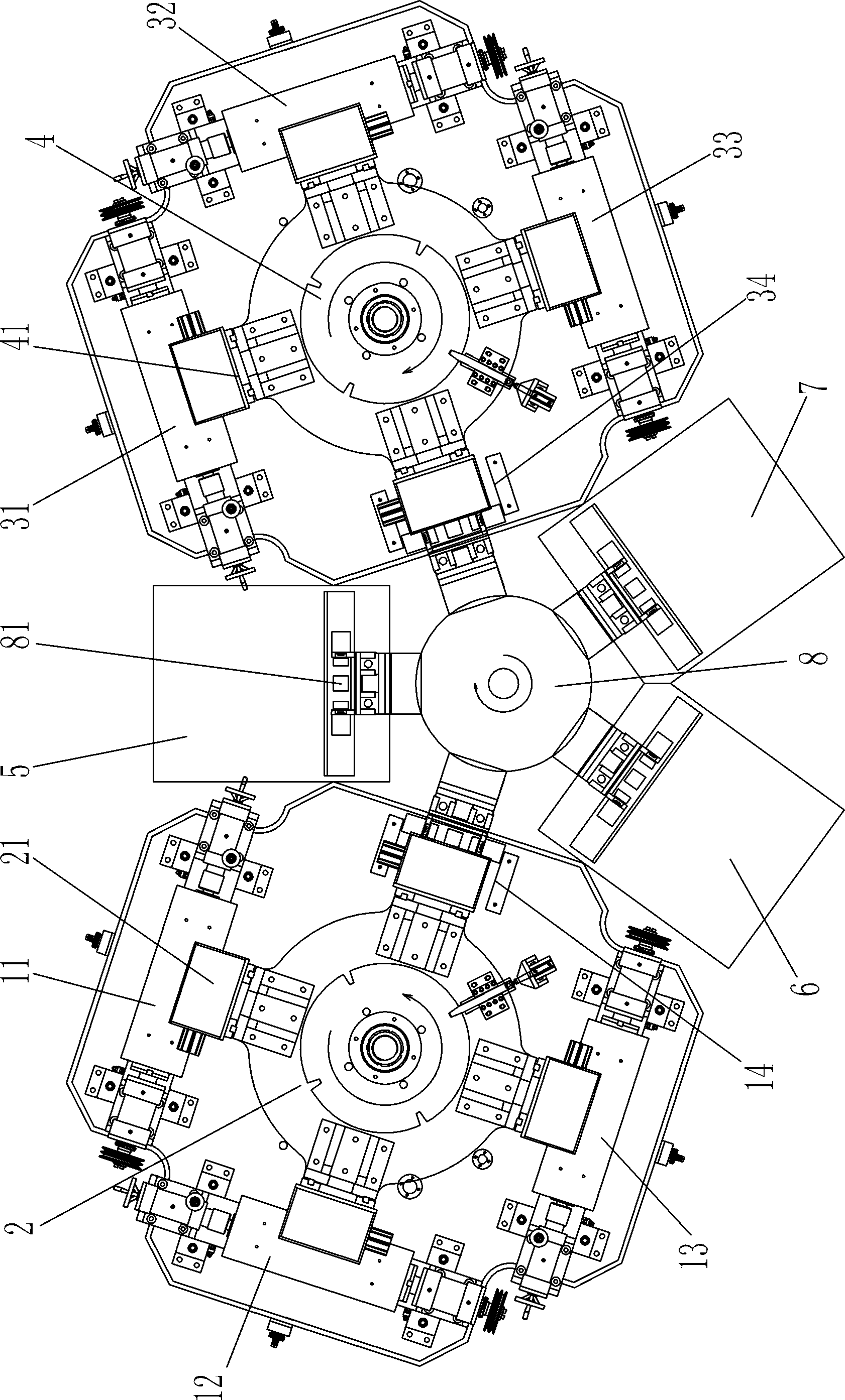
[0024] like figure 1 The shown automatic grinding and polishing system for crystal blanks includes: a first rotating frame 2, around the first rotating frame 2, there are two upper hemisphere grinding stations 11 for grinding the upper hemisphere of the crystal blank. , 12 and an upper hemisphere polishing station 13 for polishing the upper hemisphere of the crystal blank, a waiting station 14, the first rotating frame 2 can be rotated and positioned and is provided with four heads 21; The second rotating frame 4. There are two lower hemisphere grinding stations 31 and 32 for grinding the lower hemisphere of the crystal blank and a lower hemisphere polisher for polishing the lower hemisphere of the crystal blank around the second rotating frame 4. Position 33, a waiting station 34, the second rotating frame 4 can be rotated and positioned and is provided with four machine heads 41; the feeding station 6 is provided with a feeding mechanism that can fix the crystal blank on the...

Embodiment 2

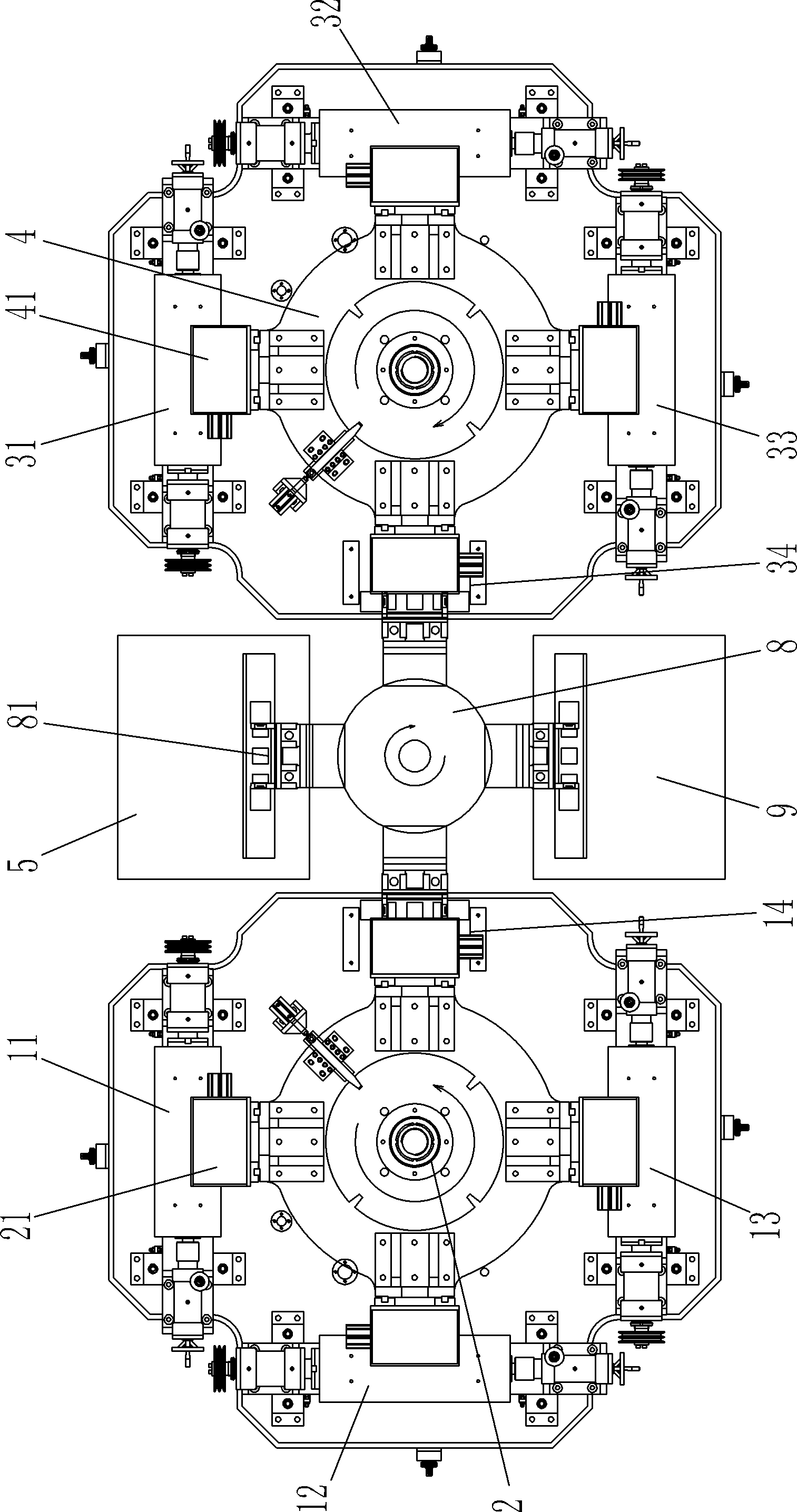
[0028] like figure 2The shown automatic grinding and polishing system for crystal blanks includes: a first rotating frame 2, around the first rotating frame 2, there are two upper hemisphere grinding stations 11 for grinding the upper hemisphere of the crystal blank. , 12 and an upper hemisphere polishing station 13 for polishing the upper hemisphere of the crystal blank, the first rotating frame 2 can be rotated and positioned and is provided with four heads 21; the second rotating frame 4 is rotated around the second The frame 4 is provided with two lower hemisphere grinding stations 31 and 32 for grinding the lower hemisphere of the crystal blank and a lower hemisphere polishing station 33 for polishing the lower hemisphere of the crystal blank. The second rotation The rack 4 can be rotated and positioned and is provided with four machine heads 41; the loading and unloading station 9 is provided with a loading and unloading material that can remove the crystal blank from t...

Embodiment 3

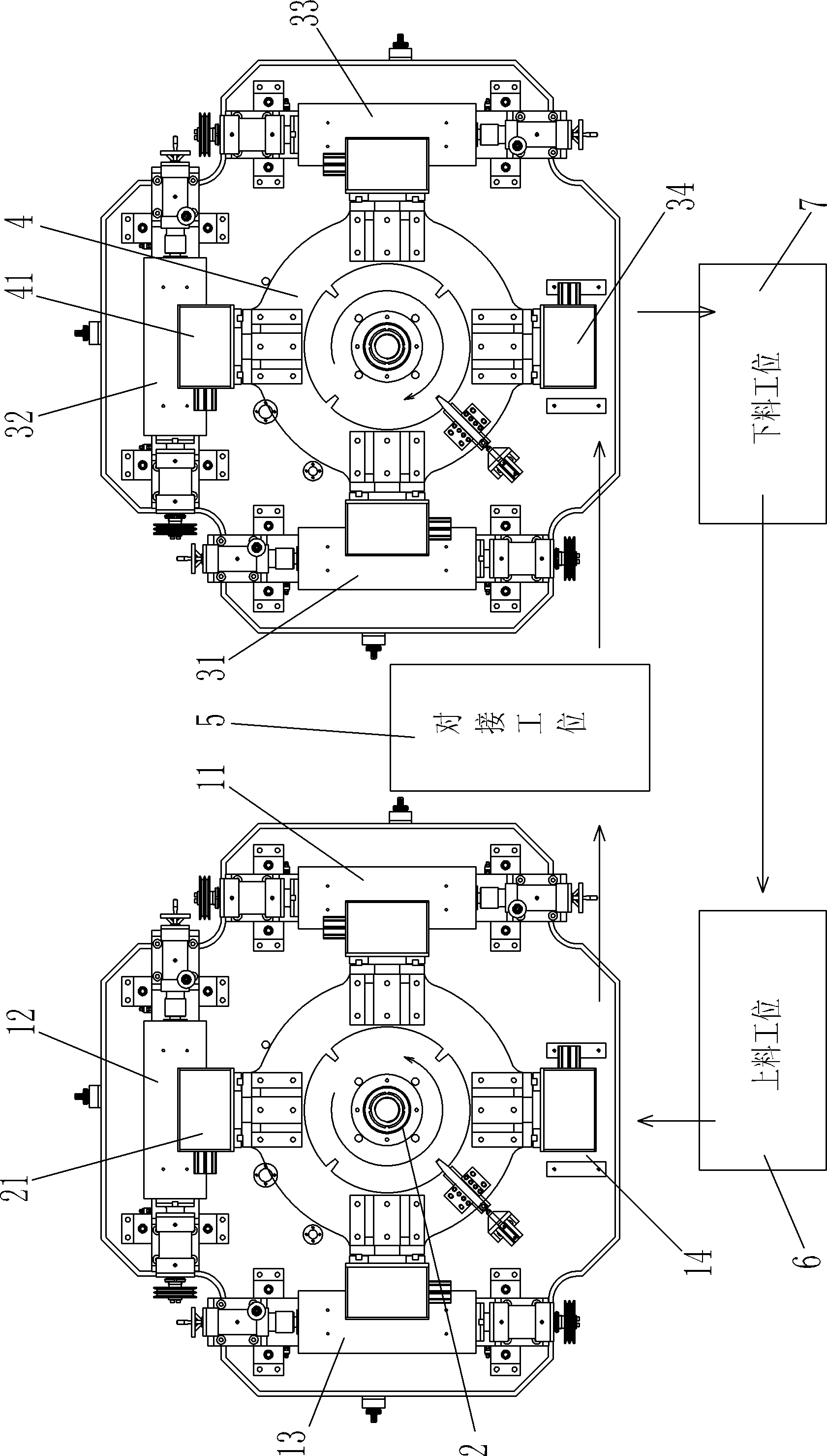
[0032] like image 3 The shown automatic grinding and polishing system for crystal blanks differs from Embodiment 1 only in that:

[0033] The transfer mechanism includes five manipulators capable of picking up and putting down clamps, and these five manipulators are respectively along the top of the loading station 6 to the top of the head of the first rotating frame 2 (located on the waiting station 14), the first rotating frame. 2 above the machine head (located on the waiting station 14) to above the docking station 5, above the docking station 5 to above the head of the second rotating frame 4 (located on the waiting station 34), and above the second rotating frame 4 Five fixed rails from the top of the machine head (located on the waiting station 34 ) to the top of the unloading station 7 , and from the unloading station 7 to the top of the loading station 6 run back and forth. Other mechanisms and working processes are similar to those in Example 1.


PUM


Abstract

An automatic grinding and polishing system for a crystal blank comprises: upper hemisphere grinding stations (11, 12) and polishing station (13) that are arranged around a first rotation rack (2), the first rotation rack (2) being provided with a handpiece (21); lower hemisphere grinding stations (31, 32) and polishing station (33) that are arranged around a second rotation rack (4), the second rotation rack (4) being provided with a handpiece (41); a loading station (6); a butt joint station (5); a discharging station (7); and a transferring mechanism capable of picking up and laying down a fixture, and sequentially transferring the fixture among the loading station (6), the handpiece (21) of the first rotation rack (2), the butt joint station (5), the handpiece (41) of the second rotation rack (4), and the discharging station (7). A grinding and polishing system is further provided, where the loading station and the discharging station are combined into a loading-discharging station. The present invention not only implements the automatic grinding and polishing processing and ensures the quality of the grinding and polishing processing, but also fully utilizes the advantages of the existing machine type, hence simplifying the complexity of mechanism actions, reducing the machine volume, and being easy to manufacture, transport, and maintain.

Description

technical field [0001] The invention relates to the field of grinding and polishing of crystal products, in particular to an automatic grinding and polishing system for crystal blanks for automatic grinding and polishing of crystal blanks. Background technique [0002] The existing multi-station crystal bevel grinding and polishing machine adopts a plurality of machine heads fixed with rhinestone fixtures to rotate for multi-station processing. For example, the patent document with publication number CN201179615Y discloses an automatic loading and unloading rhinestone bevel grinding and polishing The machine includes a frame. Two rotating frames are arranged side by side on the frame, and one head is set on each of the four sides of the rotating frame to form seven stations, which are the feeding station, the front hemisphere rough grinding station, and the front hemisphere polishing station. Position, docking station, rear hemisphere rough grinding station, rear hemisphere ...

Claims


Application Information

Patent Timeline
Patent Type & Authority Patents(China)
IPC IPC(8): B24B9/16B24B41/06
CPCB24B27/0023B24B11/02B24B29/04B24B9/16B24B27/0069
Inventor 虞卫东
Owner 虞雅仙
Why Eureka
Try Eureka