Dosing arm kinematics
A driving mechanism and adhesive technology, applied in the direction of manufacturing tools, wood processing appliances, adhesive application devices, etc., can solve problems such as outflow
- Summary
- Abstract
- Description
- Claims
- Application Information
AI Technical Summary
Problems solved by technology
Method used
Image

Examples
Embodiment approach 1
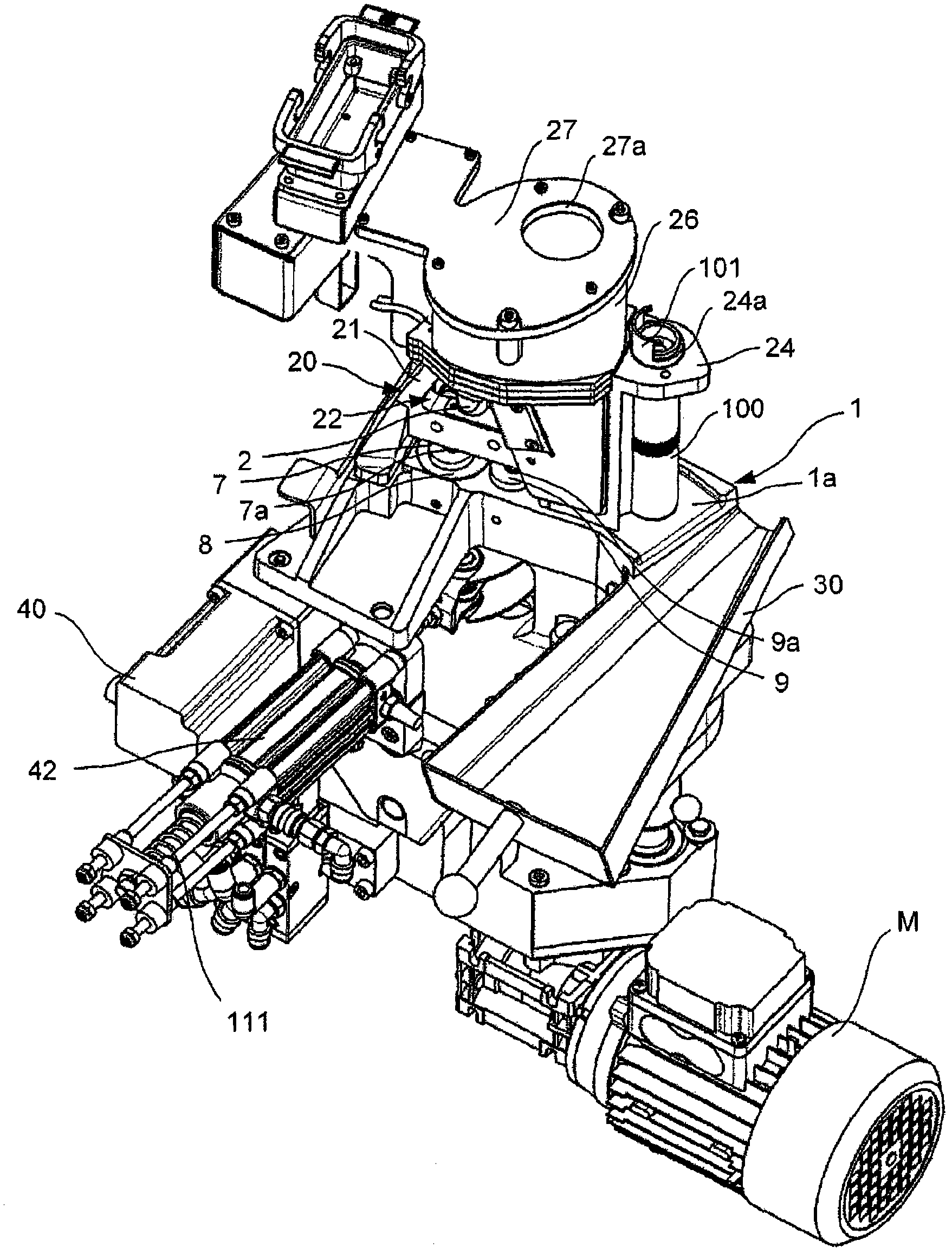
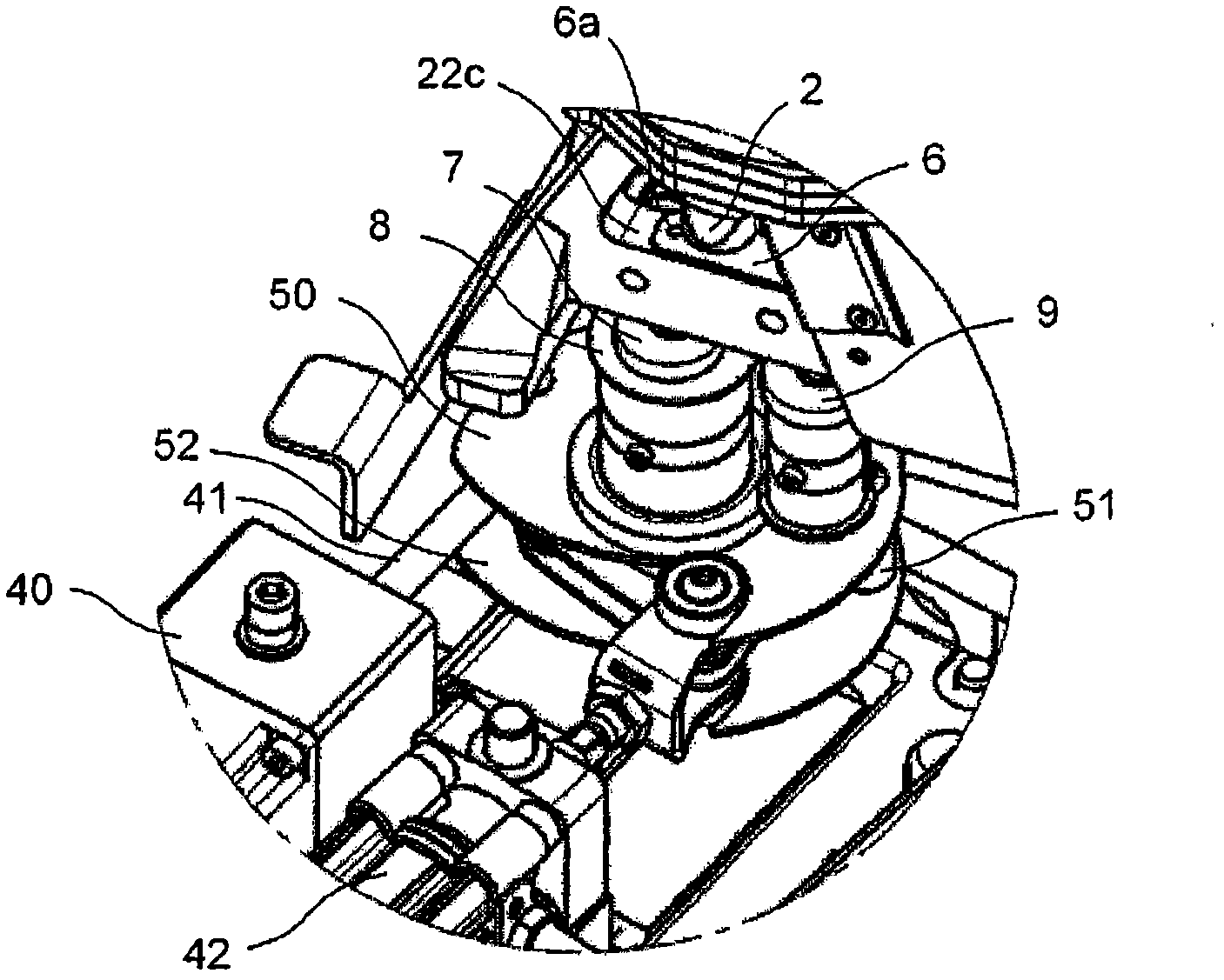
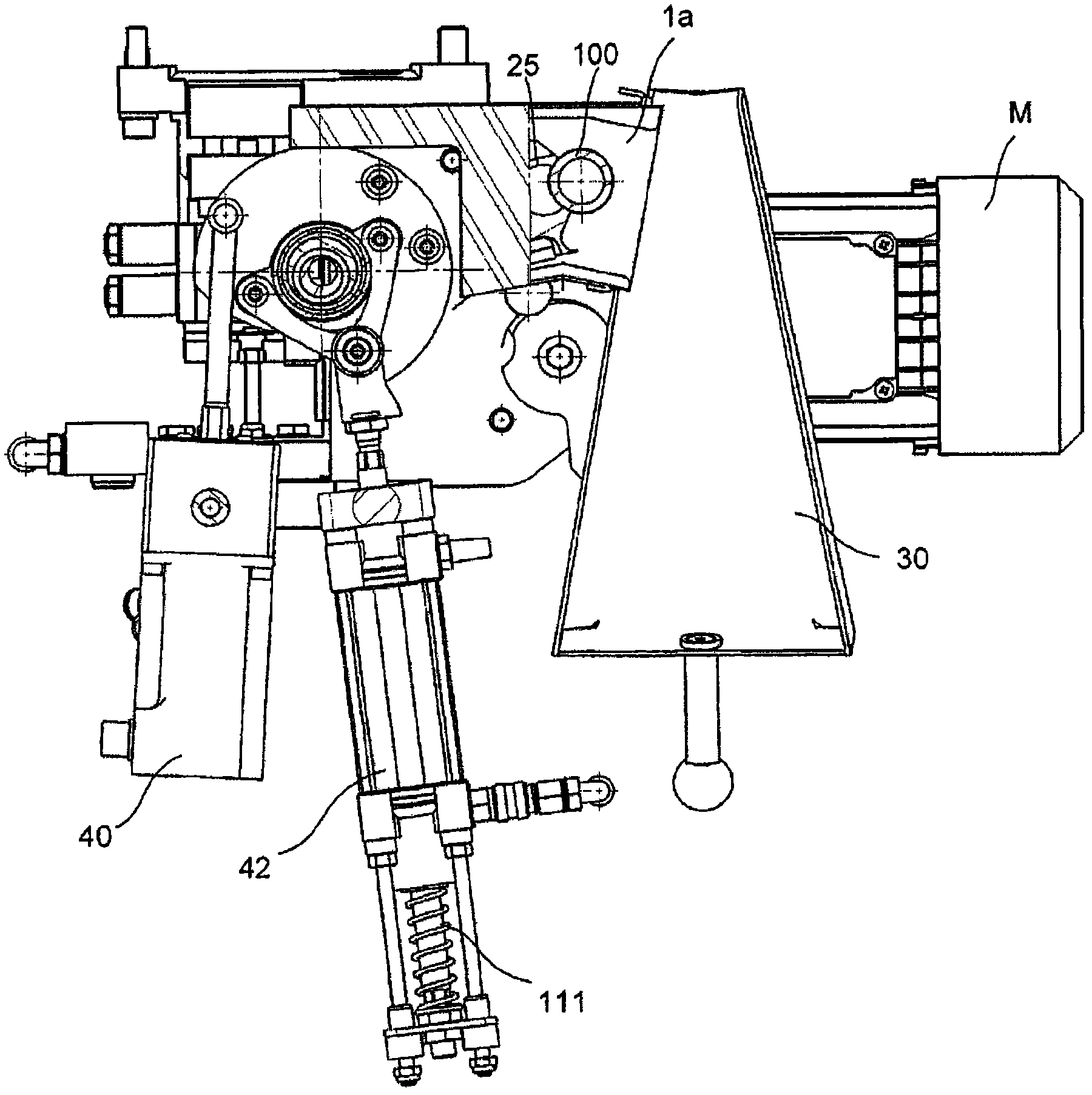
[0025] figure 1 The adhesive feed device shown comprises a base 1 on the upper surface of which is provided an outlet 1a for the adhesive. A sizing roller 100 extending substantially perpendicularly to the base 1 is provided in the region of the outlet 1a. The size roll 100 has embossings on its part or the whole surface, so that the adhesive (size) can be well received and transferred to the workpiece (not shown), and the size roll can be used in the The base 1 is installed in a rotating manner. The annular gap between the sizing roller 100 and the base 1 is small or sealed so that liquefied sizing cannot enter between the sizing roller 100 and the base 1 during operation.
[0026] A support 2 is arranged on another region of the upper surface of the base 1 . Contact shoes (not shown) are also arranged on or in the vicinity of the support. The purpose of the contact shoe is to introduce the workpiece, such as edging material, into the region of the sizing roller 100 so th...
Embodiment approach 2
[0060] Refer to the attached image 3 , 3a Another embodiment of the invention is described with 4a-4d.
[0061] Embodiment 2 of the present invention includes a base 200 similar to the foregoing Embodiment 1, above which an upper member 20A is placed. Also basically, image 3 , 3a Components in 4a to 4d that are the same as in Embodiment 1 are denoted by the same reference numerals.
[0062] For the device according to embodiment 2, in the base 200 there is a pin 201 in the region of the front eccentric shaft 9 of embodiment 1, which pin has a rolling bearing 202 on the side facing the upper part 20A, which is opposite Placed eccentrically on the axis of the pin 201 (see Figure 3a ). The rolling bearing 202 is accommodated in a groove 208 of a horizontally extending guide portion 206 . In plan view ( FIGS. 4 a 4 d ), the groove 208 is substantially in the shape of an isosceles triangle, with one rounded apex pointing in the direction of the size roller 100 .
[0063]...
Embodiment approach 3
[0070] The device according to Embodiment 3 is similar in configuration to the device according to Embodiment 2. A base 300 is thus provided, above which the pivotable upper part 20B is arranged.
[0071] However, a droplet-shaped pressure receiving member 302 is provided on a pin 301 (basically equivalent to the pin 201 in Embodiment 2) instead of a rolling bearing. The pressure member 302 is arranged eccentrically with respect to the axis of the pin 301 .
[0072] Also similar to embodiment 2, in this embodiment 3 there is additionally a pin 303 with a rod 304 which essentially corresponds to the pin 203 with rod 204 . However, a droplet-shaped pressure receiving member 305 is also provided instead of a rolling bearing to serve as a connecting member connecting the guide portion 306 , and unlike the droplet-shaped pressure receiving member 302 , the pressure receiving member 305 has two sharp ends.
[0073] The drop-shaped pressure receiving member 305 engages in the groov...
PUM
 Abstract
Description
Claims
Application Information