Conveying chain device

A conveyor chain and chain assembly technology, which is applied in the direction of conveyors, transportation and packaging, etc., can solve the problems of easy deviation, jamming, loud noise, etc., and achieve the effect of reliable work, avoiding collision, and low noise

Inactive Publication Date: 2012-07-18
WUXI KENKE HEAVY IND EQUIP
View PDF4 Cites 11 Cited by
  • Summary
  • Abstract
  • Description
  • Claims
  • Application Information

AI Technical Summary

Problems solved by technology

[0005] In view of the shortcomings of the above-mentioned prior art that the pipe material is noisy during the conveying process, it is easy to cause deviation, jamming and other phenomena, the applicant provides a conveyor chain device with a reasonable structure and easy op

Method used


Image

  • Conveying chain device
  • Conveying chain device
  • Conveying chain device

Examples


Embodiment Construction

[0016] The specific implementation manner of the present invention will be described below in conjunction with the accompanying drawings.

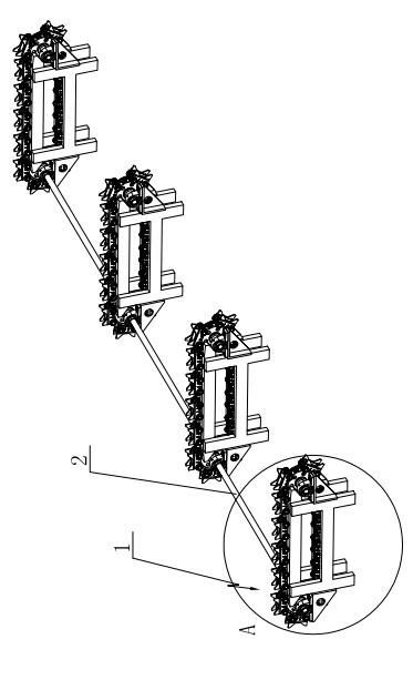
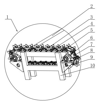
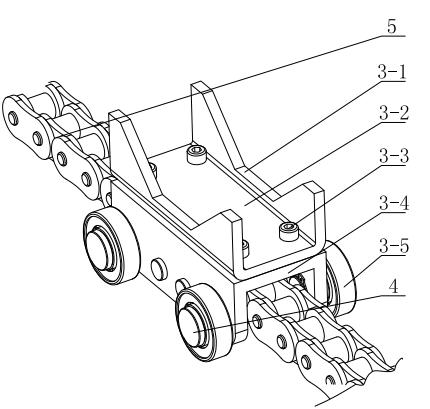
[0017] Such as figure 1 with figure 2 As shown, in a conveyor chain device according to the present invention, four sets of chain transmission mechanisms 1 are connected at intervals through transmission shafts 2, and the chain transmission mechanism 1 includes a frame 10, a sprocket 7 and a chain 5, and the two sides of the frame 10 are respectively installed The triangular support frame 9, the sprocket 7 is installed through the pin shaft 6 on the triangular support frame 9, and is supported by the bearing device 8, and the chain 5 is engaged between the two sprocket wheels 7; it also includes a trolley 3, and a plurality of trolleys 3 pass through the pin shaft 4 Evenly spaced on the chain 5, so that the trolley 3 is integrated with the chain 5;

[0018] See image 3 , the structure of the trolley 3 is as follows: including the uppe...


PUM


Abstract

The invention relates to a conveying chain device, which is characterized in that a plurality of groups of chain transmission mechanisms are connected at intervals by a transmission shaft; and each chain transmission mechanism comprises a rack, chain wheels, a chain and a plurality of trolleys, wherein triangular support frames are respectively arranged on the two sides of the rack; the chain wheels are arranged on the triangular support frames by a pin shaft; the chain is meshed between the two chain wheels; the plurality of trolleys are arranged on the chain at intervals uniformly by a pin shaft; each trolley has the following structure: an upper bottom plate, a lower bottom plate and travelling wheels; the upper bottom plate has a concave structure; trapezoid-shaped slots are arranged on the two side surface of the upper bottom plate; a groove is arranged at the bottom of the lower bottom plate; the upper bottom plate and the lower bottom plate are connected oppositely and fastened by a plurality of screws; and the chain passes through the groove at the bottom of the lower bottom plate; and the travelling wheels are installed on the left side and the right side of the lower bottom plate by a pin shaft. The conveying chain device is simple in structure, convenient to manufacture and install and low in cost.

Description

technical field [0001] The invention relates to the field of conveying equipment, in particular to a conveying chain device for pipe material conveying. Background technique [0002] During the operation of the steel pipe assembly line, due to the processing and manufacturing needs of each station in the production line, the position of the steel pipe needs to be transported. At present, steel pipes generally adopt the method of manually operating the crane to lift or rolling on the inclined plane frame in the production process. The two methods have the following disadvantages respectively: [0003] (1) Manual operation is used for driving and lifting, which has low work efficiency and high labor intensity. Due to the large volume and quality of the pipe material, there are great safety hazards during transportation; [0004] (2) When the rail platform with a slope is used to transport the pipe material by its own weight, due to the large quality of the pipe material, the ...

Claims


Application Information

Patent Timeline
IPC IPC(8): B65G17/40
Inventor 滕志中赵剑福周黎明黄承凯
Owner WUXI KENKE HEAVY IND EQUIP
Why Eureka
Try Eureka