Method and device for predicting and monitoring high-cycle fatigue life of turbine welded rotor

A welding rotor, high cycle fatigue technology, applied in the field of steam turbines

Active Publication Date: 2012-07-18
SHANGHAI POWER EQUIP RES INST
View PDF5 Cites 12 Cited by
  • Summary
  • Abstract
  • Description
  • Claims
  • Application Information

AI Technical Summary

Problems solved by technology

The existing methods for predicting and monitoring the life of steam turbine rotors provide a method for predicting and monitoring the low-cycle fatigue life of steam turbine welded rotors. For the prediction and monitoring of high-cycle fatigue life of steam turbine welded rotors, there is no suitable method and device available. use

Method used


Image

  • Method and device for predicting and monitoring high-cycle fatigue life of turbine welded rotor
  • Method and device for predicting and monitoring high-cycle fatigue life of turbine welded rotor
  • Method and device for predicting and monitoring high-cycle fatigue life of turbine welded rotor

Examples


Embodiment

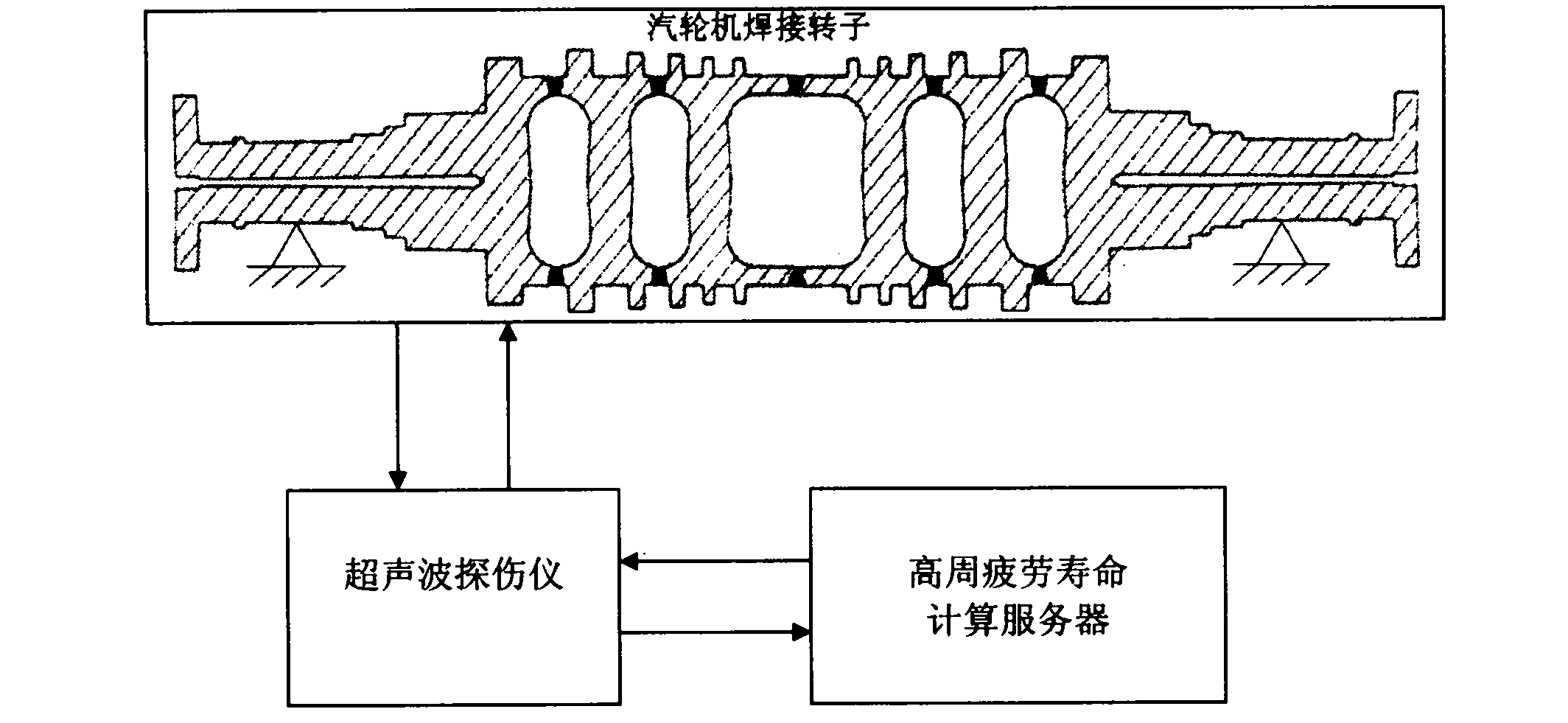
[0080] Such as figure 1 As shown, the block diagram of the steam turbine welded rotor high cycle fatigue life monitoring device of the present invention, the steam turbine welded rotor high cycle fatigue life device of the present invention is composed of an ultrasonic flaw detector 1 and a calculation server 2, and the ultrasonic flaw detector 1 is connected with the steam turbine welded rotor and the calculation server 2 connections.

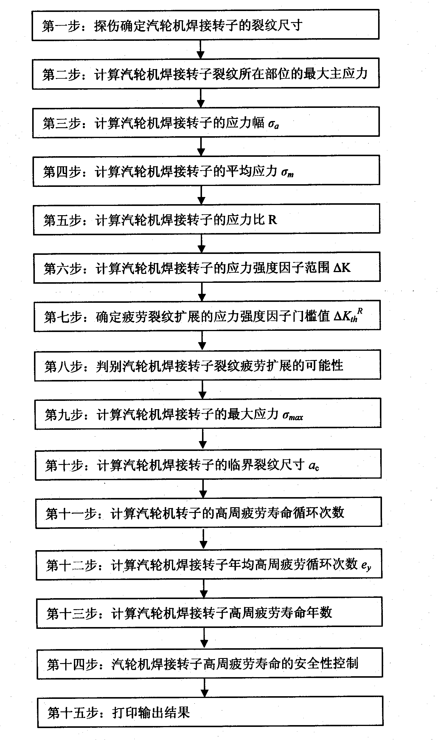
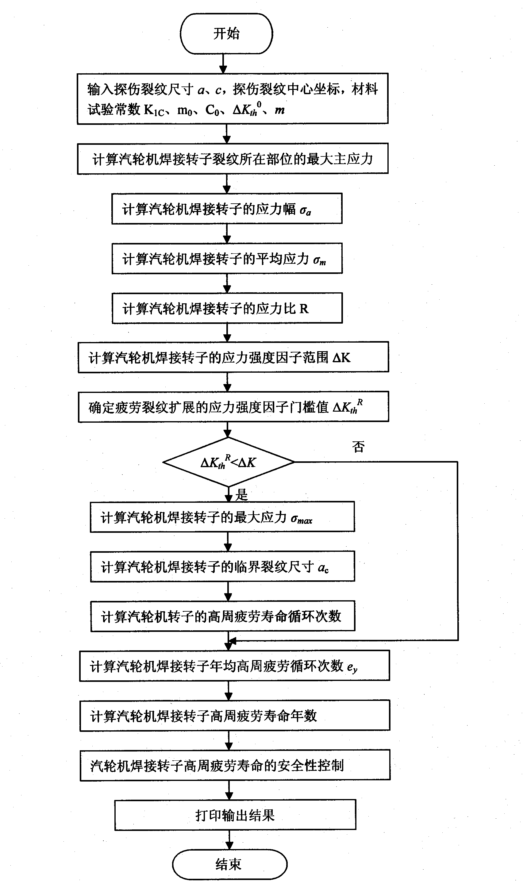
[0081] Such as figure 2 Shown, the flow chart of the steam turbine welded rotor high cycle fatigue life monitoring method of the present invention, as image 3 As shown, the computer software block diagram used by the calculation server of the present invention, the software is written in C language, installed on the calculation server of the high cycle fatigue life of the steam turbine welded rotor, and applied to the calculation and control of the high cycle fatigue life of the steam turbine welded rotor.

[0082] For a certain type of 30...


PUM


Abstract

The invention relates to a method and device for predicting and monitoring the high-cycle fatigue life of a turbine welded rotor. The device for monitoring the high-cycle fatigue life of a turbine welded rotor is characterized by consisting of an ultrasonic fault detector and a calculation server, wherein the ultrasonic fault detector is connected with the turbine rotor and the calculation server. Through the invention, quantitative prediction and quantitative monitoring of the high-cycle fatigue life of a turbine welded rotor are realized; if the high-cycle fatigue life of the turbine welded rotor is relatively short, the safety requirement on the high-cycle fatigue life of the turbine welded rotor is met by re-welding; and the technical effect on quantitatively monitoring the high-cycle fatigue life of the turbine welded rotor is realized.

Description

technical field [0001] The invention relates to a method and device for predicting and monitoring the high-cycle fatigue life of a welded rotor of a steam turbine, belonging to the technical field of steam turbines. Background technique [0002] In the steady-state rated load operation of the steam turbine, due to the action of centrifugal load and thermal load, the stable static stress in the steam turbine welded rotor is called the average stress. The welded rotor of a static large-span steam turbine with hundreds of tons, under the action of its own gravity load, generates compressive stress on the outer surface of the welded rotor above the center of gravity, and generates tensile stress on the outer surface of the welded rotor below the center of gravity. In the operation of the steam turbine, a certain point on the outer surface of the welded rotor, in addition to bearing the stable average stress caused by centrifugal force load and thermal load, when the point rotate...

Claims


Application Information

Patent Timeline
Patent Type & Authority Applications(China)
IPC IPC(8): F01D21/00
Inventor 史进渊邓志成汪勇杨宇华浩磊
Owner SHANGHAI POWER EQUIP RES INST
Why Eureka
Try Eureka