Gas-oil separator

A technology of oil and gas separator and oil and gas separation chamber, which is applied in the direction of machine/engine, engine components, mechanical equipment, etc., can solve the problems of oil channeling, poor oil return, poor separation effect, etc., and achieve obvious effects.

Inactive Publication Date: 2012-07-18
GREAT WALL MOTOR CO LTD
View PDF4 Cites 8 Cited by
  • Summary
  • Abstract
  • Description
  • Claims
  • Application Information

AI Technical Summary

Problems solved by technology

The oil-air separator is indispensable in the forced ventilation device of the crankcase, so the separation efficiency is also crucial, but the existing oil-air separator has the following disadvantages: the oil-air separator arranged on the separator housing often separates The oil and gas at the front and back are mixed together, and the separation effect is poor, resulting in poor oil return and hidden dangers of oil channeling

Method used


Image

  • Gas-oil separator
  • Gas-oil separator
  • Gas-oil separator

Examples


Embodiment Construction

[0022] Embodiments of the present invention are described in detail below in conjunction with the accompanying drawings:

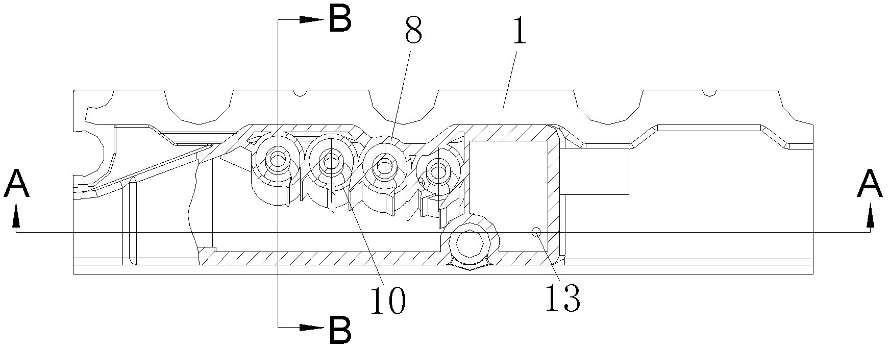
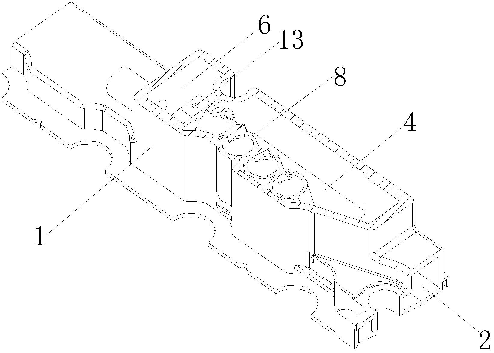
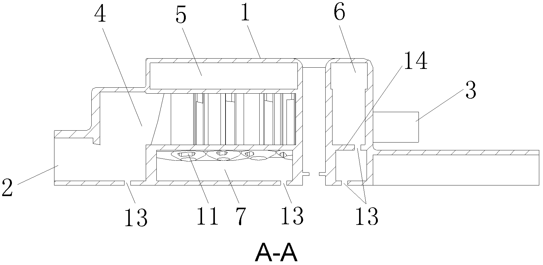
[0023] The embodiment of the present invention can be applied to the engine of the automobile, and the separator housing can be equivalent to the cylinder head cover on the engine, such as image 3 As shown, including the separator housing 1 (cylinder head cover), the left side of the separator housing 1 (cylinder head cover) is parallel to the bottom surface with an oil and gas inlet 2, and the right side is also parallel to the bottom surface with an outlet. Air port 3.

[0024] The upper side of the oil-gas separation chamber 4 in the separator housing is an air outlet chamber 5, and the lower side is an oil return chamber 6, wherein the left side of the oil-gas separation chamber 4 communicates with the air inlet 2, and the air outlet chamber 5 communicates with the air outlet 3 connected. A number of oil-gas separators 8 placed side by side are conn...


PUM


Abstract

The invention discloses a gas-oil separator and relates to the technical field of automobile engines, solving the problem of poor gas-oil separation efficiency. The gas-oil separator comprises a separator shell, wherein a gas-oil separation cavity is arranged in the separator shell; one end of the gas-oil separation cavity is communicated with a gas-oil air inlet, and the other end of the gas-oil separation cavity is communicated with an air outlet cavity; a cyclone gas-oil separator is arranged in the gas-oil separation cavity; and the upper end of the cyclone gas-oil separator is provided with an air outlet communicated with the air outlet cavity, the side face of the cyclone gas-oil separator is provided with an air inlet, and the lower end of the cyclone gas-oil separator is provided with an oil outlet. The gas-oil separator provided by the invention is applied to various automobiles and acts as a gas-oil separation mechanism of a ventilating device in an engine crankcase.

Description

technical field [0001] The invention relates to the technical field on automobile engines, in particular to an oil-gas separator on the engine. Background technique [0002] In recent years, the global requirements for the automobile industry to solve environmental protection, energy and other issues have become higher and higher, especially the emission problem has received more and more global attention. With the increasingly stringent emission regulations related to automobiles, the oil in the crankcase in the engine The emission problems caused by fog particles and exhaust gas (hydrocarbons) are also getting more and more attention. [0003] At present, in order to reduce the exhaust gas discharged from the engine and reduce the damage to the engine, the crankcase is basically ventilated. The ventilation methods of the crankcase generally include natural ventilation and forced ventilation, but natural ventilation is to ventilate the inside of the box. The gas is vented ...

Claims


Application Information

Patent Timeline
Patent Type & Authority Applications(China)
IPC IPC(8): F01M13/04
Inventor 沈吉瑞柴晓娜
Owner GREAT WALL MOTOR CO LTD
Why Eureka
Try Eureka