Spatial three-dimensional vision-computing verification method

A technology of 3D vision and verification method, which is applied in the field of spatial 3D vision computing verification, and can solve the problems that the visual system error cannot be given quantitatively.

Active Publication Date: 2012-07-18
深圳了然视觉科技有限公司
View PDF7 Cites 14 Cited by
  • Summary
  • Abstract
  • Description
  • Claims
  • Application Information

AI Technical Summary

Problems solved by technology

However, this verification method does not quantify the error in the measurement made by the vision system.

Method used


Image

  • Spatial three-dimensional vision-computing verification method
  • Spatial three-dimensional vision-computing verification method
  • Spatial three-dimensional vision-computing verification method

Examples


Embodiment Construction

[0027] The space three-dimensional visual computing verification method of the present invention is described in detail below in conjunction with the accompanying drawings:

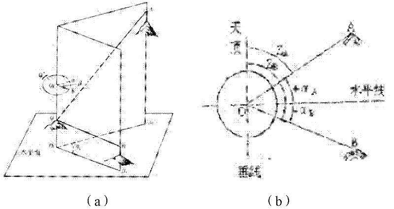
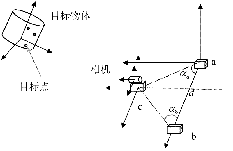
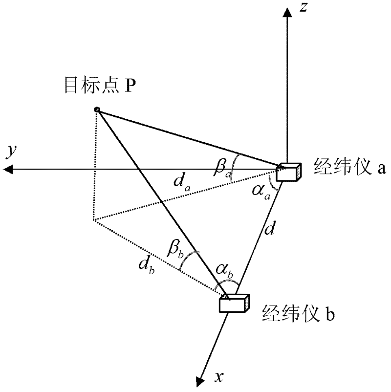
[0028] First, the coordinate system involved in the present invention is briefly described. see figure 2 As shown, the reference coordinate system is constructed by theodolite a and theodolite b, and its main purpose is to link other rectangular coordinate systems. The target object coordinate system, with a point on the target object as the origin, is used to describe the coordinates of the target point in its own coordinate system. The camera coordinate system is a Cartesian coordinate system established with the optical center as the origin and the optical axis as the z direction. At the same time, each theodolite itself also establishes a rectangular coordinate system.

[0029] The implementation steps of the present invention are described in detail below:

[0030] The first step is to establish...


PUM


Abstract

The invention provides a spatial three-dimensional vision-computing verification method. In a verification experiment, a reference coordinate system is formed by two theodolites a and b, a third theodolite c and a reference coordinate only have a translational relation. A camera is fixed on the theodolite c, and the relation between a camera coordinate system and a theodolite c coordinate system is obtained. The coordinate of three target points on a spatial target object under an own object coordinate system is given, then coordinates of three characteristic points under the reference coordinate system are obtained by utilizing the theodolites a and b, and further the relation between the object coordinate system and the reference coordinate system is solved. Finally, the relation between the target object coordinate system and the camera coordinate system is obtained as a reference value of a three-dimensional position of the target object. The reference value is used for verifying the three-dimensional position of the target object solved by other algorithms. The coordinates of spatial points under the camera coordinate system are obtained by utilizing the reference values of the position of the target object, and are projected to an image plane so as to verify the parameter calibrated by a vision system in the camera.

Description

technical field [0001] The invention belongs to the field of computer vision measurement and measurement system algorithm verification, and relates to a spatial three-dimensional vision calculation verification method. Background technique [0002] The algorithm of using image-based computer vision method to calculate the internal parameters of the camera and the three-dimensional pose of the space target is very common in the vision system. There are methods of artificially adding features on the surface of the target object, and there are also corner points of the target object itself. , Texture feature method. [0003] The verification of the calculation results of these algorithms is usually to use the calculated camera internal parameters and three-dimensional pose parameters to substitute into the camera projection model, and compare the projection results of the features on the target object with the features extracted from the original image, so as to indirectly veri...

Claims


Application Information

Patent Timeline
Patent Type & Authority Applications(China)
IPC IPC(8): G01C25/00
Inventor 王飞张雪涛杨海伟何永健郭宇郑南宁
Owner 深圳了然视觉科技有限公司
Why Eureka
Try Eureka