Faraday mirror optical current transformer for transformer substation

A technology for current transformers and substations, which is applied in the directions of voltage/current isolation, measuring current/voltage, instruments, etc. It can solve the problems of weak anti-linear birefringence interference ability, unfavorable substation high-voltage current, and large induction signal interference. Effect of enhanced linear birefringence interference capability

Inactive Publication Date: 2012-07-18
CHENGDU CHUANGTU TECH
View PDF2 Cites 2 Cited by
  • Summary
  • Abstract
  • Description
  • Claims
  • Application Information

AI Technical Summary

Problems solved by technology

Traditional optical current transformers used in substations, the number of times the light in the optical current sensing head surrounds the current-carrying conductor is one time. According to the Ampere loop theorem, its ability to resist linear birefringence interference is weak, so the interference of the sensing signal Larger, it cannot truly reflect the change of the high-voltage current flowing in the current-carrying conductor, which is not conducive to the management personnel to accurately understand the high-voltage current situation of the substation, and serious cases may lead to high-voltage accidents

Method used


Image

  • Faraday mirror optical current transformer for transformer substation
  • Faraday mirror optical current transformer for transformer substation

Examples


Embodiment Construction

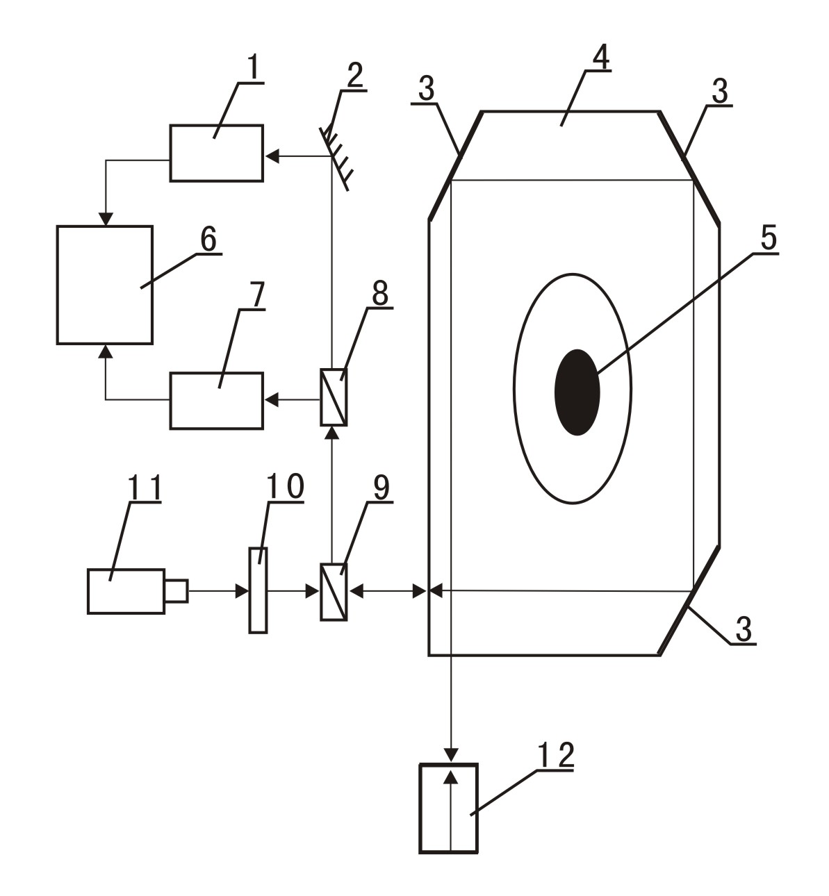
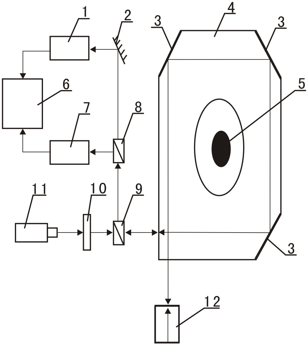
[0012] The present invention will be further described below in conjunction with accompanying drawing:

[0013] As shown in the drawings, the present invention includes an LED light source 11, a polarizing prism 10, a non-polarizing beam splitter 9, an optical current sensing head 4, a Faraday mirror 12, a polarizing beam splitter 8, a first photoelectric converter 1, a second Photoelectric converter 7, plane mirror 2 and signal processing circuit 6, polarizing prism 10 is arranged between LED light source 11 and non-polarizing beam splitter 9, and non-polarizing beam splitter 9 is arranged between polarizing prism 10 and optical current sensor head 4 Between the incident planes, the polarized light exit optical axis of the non-polarized beam splitter 9 coincides with the incident optical axis of the polarized beam splitter 8, and the Faraday mirror 12 is arranged below the exit plane of the optical current sensor head 4, and the mirror surface of the Faraday mirror 12 and The...


PUM


Abstract

The invention discloses a faraday mirror optical current transformer for a transformer substation. The faraday mirror optical current transformer comprises a light-emitting diode (LED) light source, a polarizing prism, an optical current sensing head, a polarization beam splitter, a first photoelectric transducer, a second photoelectric transducer, a signal processing circuit, a non-polarization beam splitter, and a faraday mirror; the non-polarization beam splitter is arranged between the incident surface of the polarizing prism and the incident surface of the optical current sensing head; a polarized light emergence optical axis of the non-polarization beam splitter is coincided with the incident optical axis of the polarization beam splitter; the faraday mirror is arranged below the emergence surface of the optical current sensing head; and the mirror surface of the faraday mirror is opposite and parallel to the emergence surface of the optical current sensing head. Due to the polarized light reflection action of the faraday mirror, light surrounds a current-carrying conductor twice in the optical current sensing head, and the polarization plane is rotated 90 degrees before and after reflection; and according to an Ampere circuital theorem, linear birefringence interference resistance capacity of the faraday mirror optical current transformer is enhanced obviously.

Description

technical field [0001] The invention relates to an optical current transformer used in a substation, in particular to a Faraday mirror optical current transformer used in a substation with strong anti-linear birefringence interference capability. Background technique [0002] An optical current transformer is a transformer that uses an optical path to induce current and obtains an output current through signal processing. In substations, optical current transformers are used to sense high-voltage currents and the induced currents are used for monitoring and management of substations, so that managers can understand the high-voltage current conditions of substations in real time, which is convenient for management and prevention of high-voltage accidents. [0003] Optical current transformers used in substations are composed of LED light sources, polarizing prisms, optical current sensing heads, and signal processing circuits. The light passes through the optical current sens...

Claims


Application Information

Patent Timeline
Patent Type & Authority Applications(China)
IPC IPC(8): G01R15/24G01R19/00
Inventor 车华明马晓英车小华
Owner CHENGDU CHUANGTU TECH
Why Eureka
Try Eureka