Light-emitting Device

A light-emitting device and self-luminous technology, which is applied in the direction of electrical components, circuits, organic semiconductor devices, etc., can solve problems such as poor uniformity of light emission, and achieve the effect of uniform light output

Inactive Publication Date: 2012-07-18
AU OPTRONICS CORP
View PDF3 Cites 7 Cited by
  • Summary
  • Abstract
  • Description
  • Claims
  • Application Information

AI Technical Summary

Problems solved by technology

[0003] However, when the organic electroluminescent device develops towards a large size, the luminescence uniformity of the organic electroluminescent device is often poor
Therefore, there are still some problems in making large-scale organic electroluminescent devices for application in lighting devices

Method used


Image

  • Light-emitting Device
  • Light-emitting Device
  • Light-emitting Device

Examples


Embodiment Construction

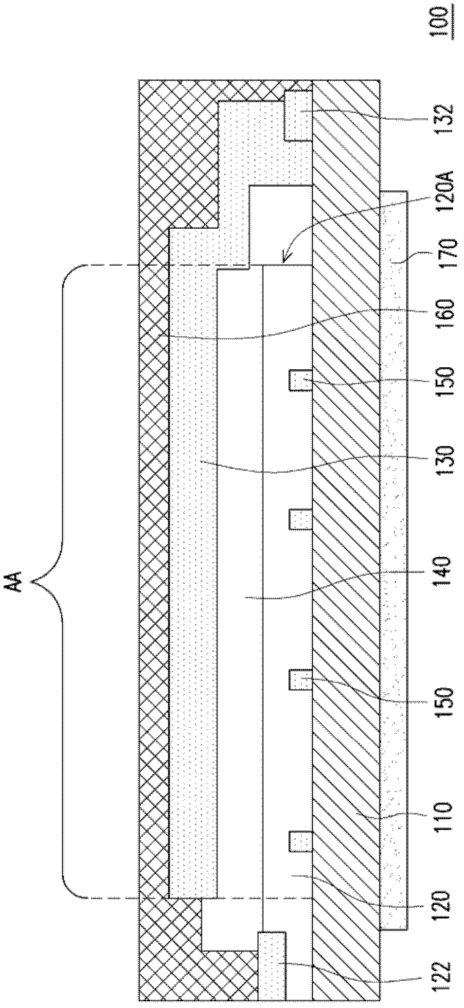
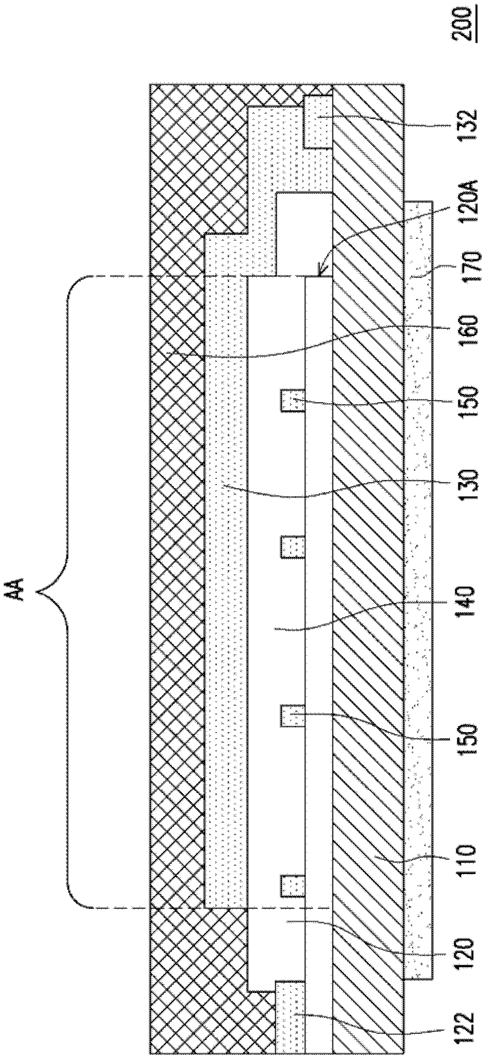
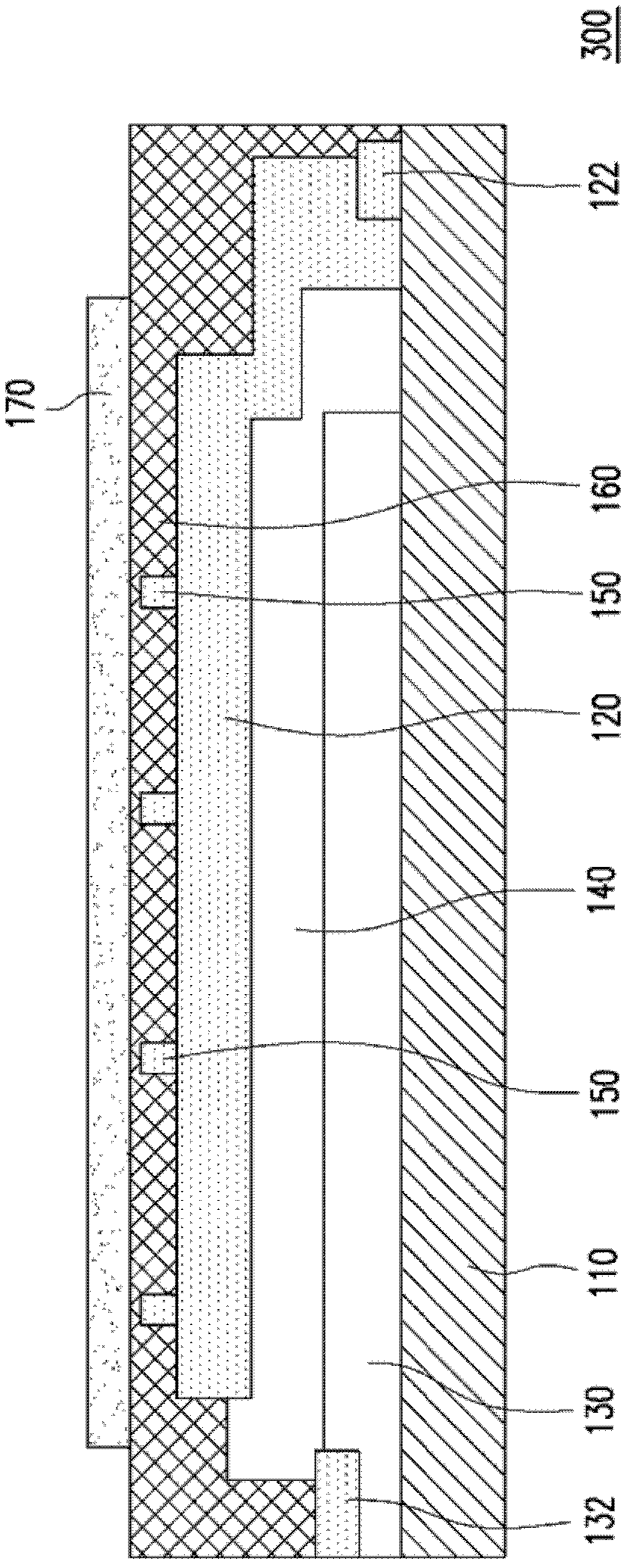
[0048] Figure 1 to Figure 5 Shown are cross-sectional schematic views of light emitting devices of several embodiments of the present invention. Please refer to figure 1 The light emitting device 100 includes a substrate 110 , a first conductive layer 120 , a second conductive layer 130 , a self-luminous layer 140 , a first auxiliary conductive pattern layer 150 , a protective substrate 160 and a light extraction layer 170 . The first conductive layer 120 , the second conductive layer 130 , the self-luminous layer 140 , the first auxiliary conductive pattern layer 150 , the protection substrate 160 and the light extraction layer 170 are all disposed on the substrate 110 .

[0049] The first conductive layer 120, the second conductive layer 130 and the self-luminous layer 140 are all stacked on the same side of the substrate 110, that is, the first surface of the substrate 110 (or called the inner surface of the substrate 110), and the self-luminous layer 140 is disposed on t...


PUM


Abstract

The invention discloses a light-emitting device, including a base plate, a first conductive layer, a second conductive layer, a self-light-emiting layer and a first auxiliary conductive pattern layer. The first conductive layer and the second conductive layer are both arranged on the base plate. The self-light-emiting layer is arranged between the first conductive layer and the second conductive layer, and defines a light-emitting area on the base plate. The resistance of first auxiliary conductive pattern layer is contacted is smaller than that of the first conductive layer. The ratio of the circumference (micrometer) of the first auxiliary conductive pattern layer at the light-emitting area to the area of the (micrometer<2>) light-emitting area is not more than 0.0262 (1 / micrometer).

Description

technical field [0001] The present invention relates to a light emitting device, and in particular to a self-illuminating light emitting device. Background technique [0002] Organic electroluminescence (organic electroluminescence) devices have excellent characteristics such as thinness, self-luminescence, low power consumption, no need for backlight, no viewing angle limitation, and high response rate. They have been regarded as the rising stars of flat-panel displays. In addition, passive organic light-emitting devices can be formed on thin, flexible substrates, so they are also very suitable for lighting. When the rendering index) is higher than about 80, it has the opportunity to replace general lighting sources, so organic light-emitting devices will play a very important role in lighting equipment. [0003] However, when the organic electroluminescent device develops toward a large size, the uniformity of light emission of the organic electroluminescent device is oft...

Claims


Application Information

Patent Timeline
Patent Type & Authority Applications(China)
IPC IPC(8): H01L51/50H01L51/52
CPCH01L51/5212H01L51/5228H01L51/50H01L51/52H01L2251/5361H10K50/814H10K50/824
Inventor 林振祺江伯轩吴长晏林俊良
Owner AU OPTRONICS CORP
Why Eureka
Try Eureka