Power factor correction (PFC) control circuit and method and PFC circuit

A technology for controlling circuits and circuits, applied in the field of control, can solve problems such as low total harmonic distortion

Active Publication Date: 2012-07-18
INVENTRONICS HANGZHOU
View PDF2 Cites 27 Cited by
  • Summary
  • Abstract
  • Description
  • Claims
  • Application Information

AI Technical Summary

Problems solved by technology

[0010] However, when the input terminal of the PFC circuit (that is, the input terminal of the rectifier bridge) or the output terminal of the rectifier bridge is provided with a filter capacitor, such as image 3 The first filter

Method used


Image

  • Power factor correction (PFC) control circuit and method and PFC circuit
  • Power factor correction (PFC) control circuit and method and PFC circuit
  • Power factor correction (PFC) control circuit and method and PFC circuit

Examples


Embodiment Construction

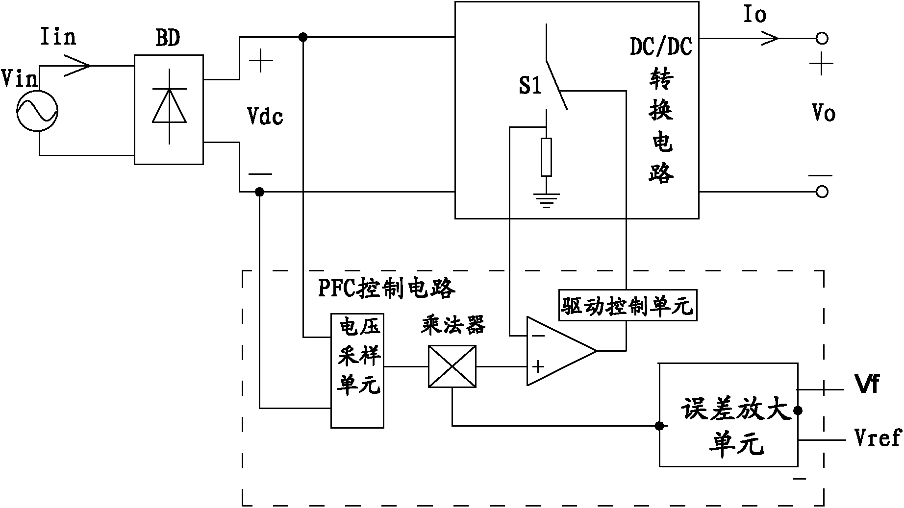
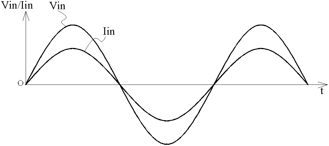
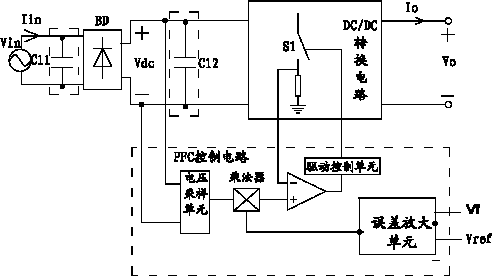
[0051] When the input end of the PFC circuit (that is, the input end of the rectifier bridge) or the output end of the rectifier bridge is provided with a filter capacitor, for example image 3 The first filter capacitor C11 and the second filter capacitor C12 shown in ; the voltage sampling signal Via in the PFC control circuit will have a DC bias ΔV, such as Figure 4 . In this way, the current reference signal Vx of the main switching tube S1 also has a DC bias, so that the input current Iin of the PFC circuit cannot approach zero near the zero crossing of the grid voltage Vin.

[0052] At the same time, since the input terminal of the PFC circuit (that is, the input terminal of the rectifier bridge) or the output terminal of the rectifier bridge is provided with a filter capacitor, there is a phase difference between the input current Iin of the PFC circuit and the grid voltage Vin, and the input current of the PFC circuit The phase of Iin leads the grid voltage Vin.

[...


PUM


Abstract

The invention discloses a power factor correction (PFC) control circuit and method and a PFC circuit. The PFC control circuit is used for controlling the connection and disconnection of a main switch tube of a direct current (DC)/DC converting circuit in the PFC circuit. The PFC circuit also comprises a rectifier bridge, wherein the rectifier bridge is used for rectifying power grid voltage; output ends of the rectifier bridge are correspondingly connected with the input end of the DC/DC converting circuit; and a filtering capacitor is arranged between two input ends or two output ends of the rectifier bridge. The PFC control circuit comprises an error amplifying unit, a multiplying unit, a comparator, a driving control unit and a voltage sampling correction unit, wherein the voltage sampling correction unit is used for sampling the input voltage of the DC/DC converting circuit, performing phase lag on a first input voltage sampling signal acquired by sampling to acquire a second input voltage sampling signal, and outputting the acquired second input voltage sampling signal to a first input end of the multiplying unit. By the technical scheme, the power factor (PF) value of the PFC circuit can be increased, and the total harmonic distortion (THD) value of the PFC circuit can be reduced.

Description

technical field [0001] The present application relates to the control field, in particular to a power factor correction (PFC, Power Factor Correction) control circuit and method, and a PFC circuit. Background technique [0002] In the prior art, the commonly used PFC circuit refers to figure 1 . Among them, after the grid voltage Vin passes through the rectifier bridge BD, the rectified sinusoidal half-wave voltage is used as the input voltage Vdc of the direct current / direct current (DC / DC) conversion circuit, and is input into the DC / DC conversion circuit, and the DC / DC conversion circuit The main switch S1 is turned on or off under the control of the PFC control circuit, so that the input current Iin of the PFC circuit follows the phase change of the grid voltage Vin. The ideal relationship between the input current Iin and the grid voltage Vin is as follows: figure 2 shown. [0003] figure 1 The PFC control circuit in includes: [0004] The first input end of the v...

Claims


Application Information

Patent Timeline
IPC IPC(8): H02M7/12H02M3/10H02M1/42
CPCY02B70/126Y02B70/10Y02P80/10
Inventor 葛良安姚晓莉
Owner INVENTRONICS HANGZHOU
Why Eureka
Try Eureka