
Vibrating armature pump

A technology of reciprocating motion and pump pistons, which is applied in the direction of pumps, pump components, variable capacity pump components, etc., can solve the problems of unfavorable cost and trouble, and achieve the effect of saving processing time and cost

Inactive Publication Date: 2012-07-18
VERMIETUNGSGEMEINSCHAFT HARALD SCHROTT & SYSKO AG
View PDF9 Cites 2 Cited by
  • Summary
  • Abstract
  • Description
  • Claims
  • Application Information

AI Technical Summary

Problems solved by technology

[0006] However, this has the disadvantage that producing corresponding undercuts or carrying out joining process steps is complex and therefore economically unfavorable

Method used


Image

  • Vibrating armature pump
  • Vibrating armature pump
  • Vibrating armature pump

Examples


Embodiment Construction

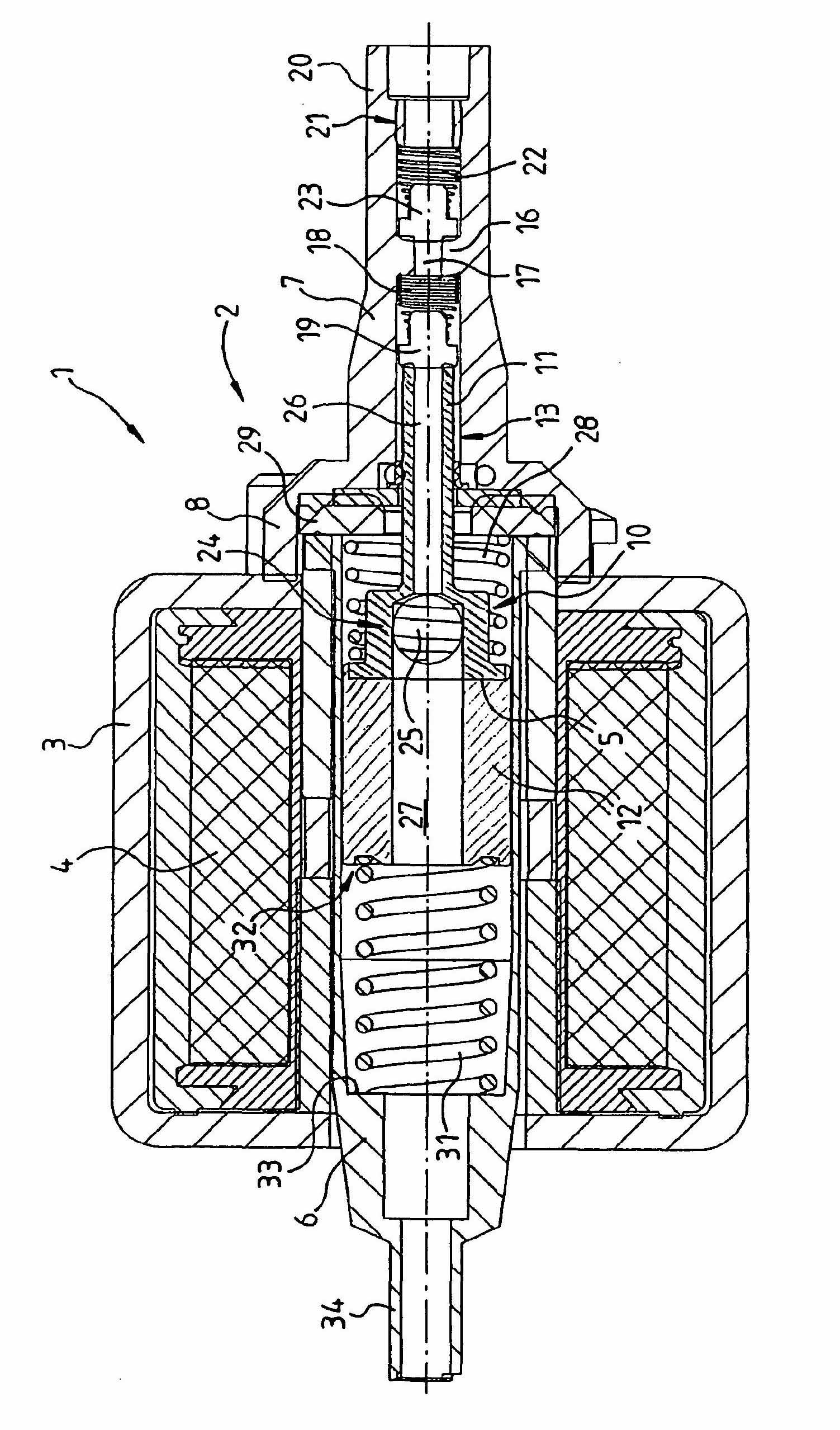
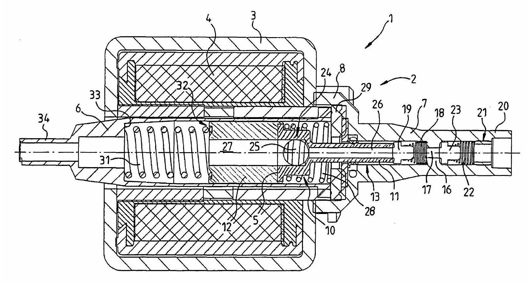
[0026] according to figure 1 The reciprocating pump 1 comprises a two-part pump housing 2 which is fixed on a yoke 3 of an electromagnetic coil 4 .

[0027] The pump housing 2 comprises a tubular armature receptacle 6 , which extends inside the coil 4 , and a cylinder part 7 which bears against the yoke 3 via a flange 8 .

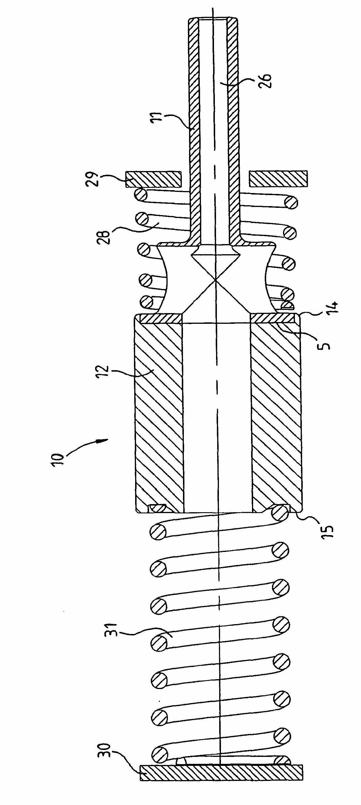
[0028] The pump piston unit or pump piston 10 penetrates into the pump housing 2 and comprises a pump part or piston part 11 and a drive part or magnetic part 12 . The piston part 11 is of tubular design and has an axial through-bore, and is immersed in a cylinder 13 which is formed in the cylinder part 7 .

[0029] During operation, the pump piston 10 and thus the piston part 11 executes a cyclic axial movement in the direction of the double arrow A, ie the pump piston oscillates periodically back and forth in the axial direction.

[0030] On the side opposite the magnetic part 12 , the cylinder 13 is closed by means of a cross arm 16 which has a central...


PUM


Abstract

The invention relates to a vibrating armature pump having a pump housing, which comprises a cylinder for receiving a substantially linearly displaceable pump piston unit (10). The pump piston unit (10) comprises at least one pump element (11) for pumping the pumping fluid and a drive element (12) for driving the pump element (11). Both elements are designed separately and arranged loosely one behind the other.

Description

technical field [0001] The invention relates to a reciprocating pump with a pump housing according to the preamble of claim 1 , comprising a cylinder for accommodating a substantially linearly displaced pump piston unit. Background technique [0002] Reciprocating pumps are characterized by a piston that oscillates to and fro on an axis of motion, which piston consists at least partially of a magnetic or magnetizable material and is driven by means of an electromagnetic coil. [0003] The piston of the reciprocating pump squeezes out the fluid, in particular water, located in the cylinder when immersed in the cylinder. When the piston extends out of the cylinder, the cylinder is filled again with fluid or water, whereby a cyclic pumping action can be achieved during the pump oscillating process. [0004] Due to this working principle, it is necessary to make the cylinder chamber have a fluid-tight structure. This sealing must be ensured at every point of the piston, so the...

Claims


Application Information

Patent Timeline
Patent Type & Authority Applications(China)
IPC IPC(8): F04B17/04F04B53/14
CPCF04B53/14F04B17/046
Inventor R·隆斯基
Owner VERMIETUNGSGEMEINSCHAFT HARALD SCHROTT & SYSKO AG
Learn More