Optical projection tomography method based on helical scanning track

A technology of optical projection tomography and helical scanning, which is applied in the fields of diagnosis, medical science, diagnostic recording/measurement, etc. It can solve the problems that slender objects cannot be imaged with high resolution and long objects cannot be finely imaged, so as to improve the accuracy of axial imaging , Guaranteed imaging accuracy, and the effect of expanding the imaging field of view

Active Publication Date: 2012-07-25
INST OF AUTOMATION CHINESE ACAD OF SCI
View PDF7 Cites 6 Cited by
  • Summary
  • Abstract
  • Description
  • Claims
  • Application Information

AI Technical Summary

Problems solved by technology

[0006] In order to solve the problem that optical projection tomography circular orbit scanning cannot finely image long objects, the present invention provides an optical projection tomography method based on helical scanning orbit, which improves the optical projection tomography by performing three-dimensional imaging on the projection data of helical scanning. Imaging Field of View, Accuracy and Speed ​​of Imaging Long Objects
[0008] The present invention performs three-dimensional tomographic imaging on the spiral orbit projection data collected by the optical projection tomography system. By using the spiral scanning method, this embodiment expands the field of view of the optical projection tomographic imaging from a cube to a cuboid, effectively improving the axial imaging accuracy and solving the problem of solves the problem that slender objects cannot be imaged with high resolution

Method used


Image

  • Optical projection tomography method based on helical scanning track
  • Optical projection tomography method based on helical scanning track
  • Optical projection tomography method based on helical scanning track

Examples


Embodiment Construction

[0020] In order to make the object, technical solution and advantages of the present invention clearer, the present invention will be described in further detail below in conjunction with specific embodiments and with reference to the accompanying drawings. While illustrations of parameters including particular values ​​may be provided herein, it should be understood that parameters need not be exactly equal to the corresponding values, but rather may approximate the values ​​within acceptable error margins or design constraints.

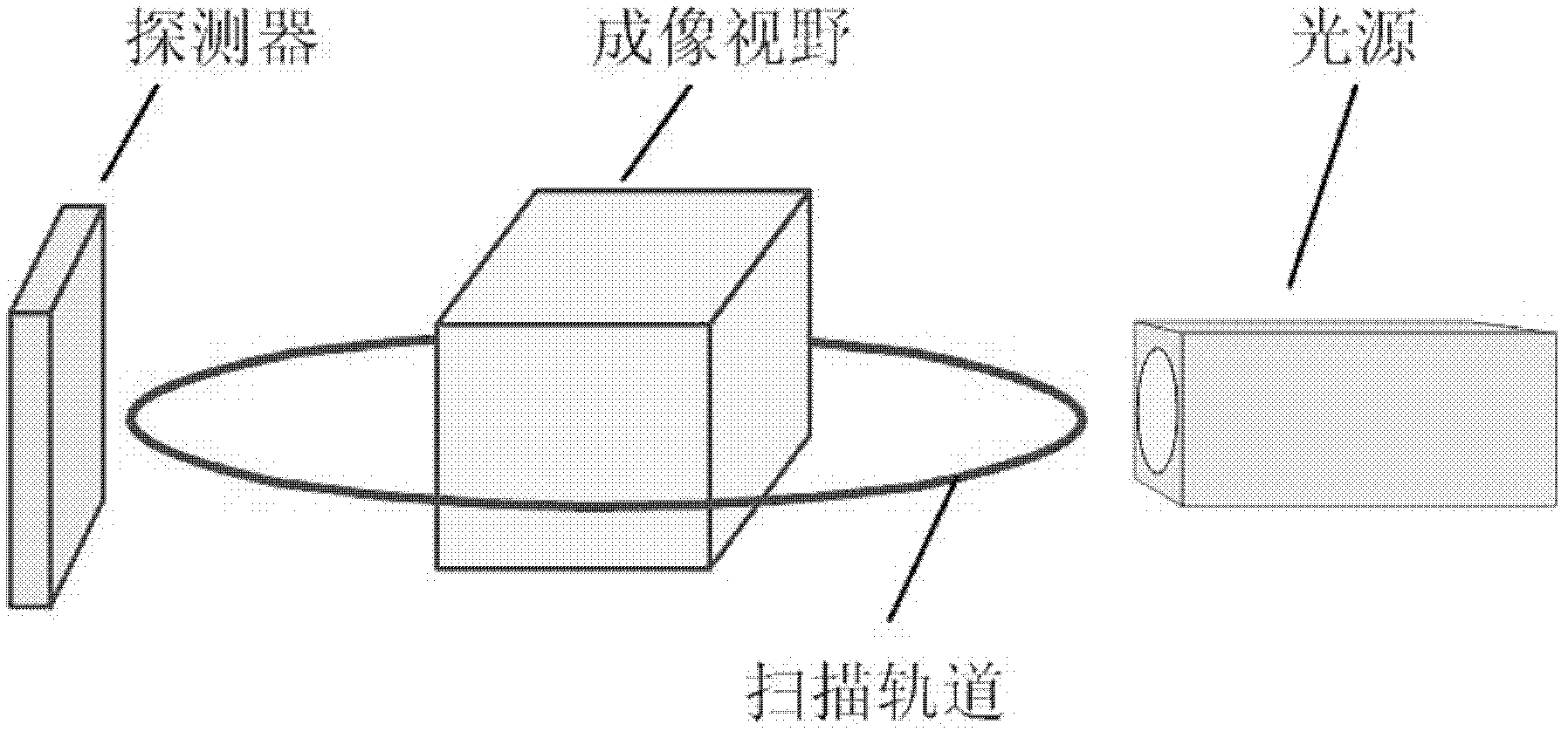
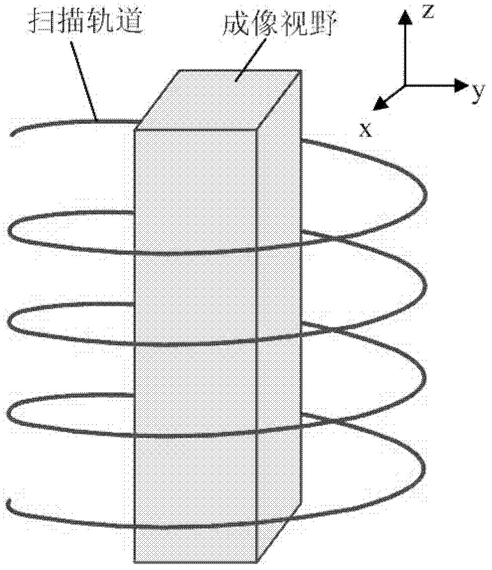
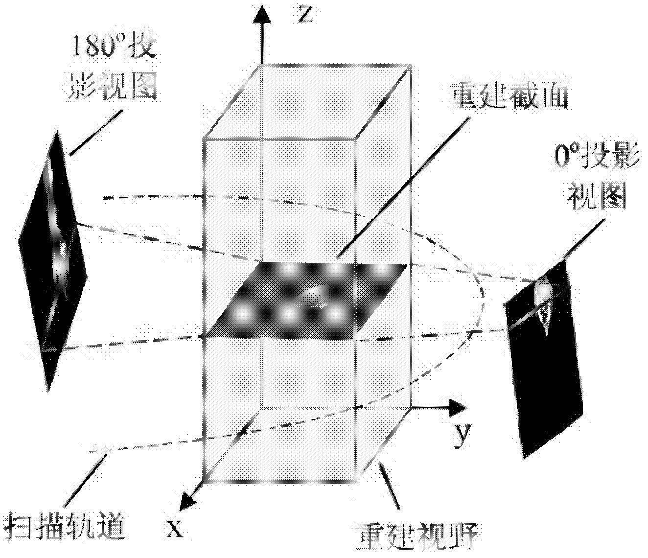
[0021] The invention is an optical projection tomography method based on a helical scanning track. The invention is specially aimed at the projection data collected by an optical projection tomography system in a spiral orbit scanning mode, and performs three-dimensional tomography imaging to expand the imaging field of view. Such as Figure 1a As shown, the current optical projection tomography generally adopts a circular orbital scanning method, a...


PUM


Abstract

The invention discloses an optical projection tomography method based on a helical scanning track. The projection data obtained by an optical projection tomography (OPT) system in a helical scanning manner is rearranged to be transformed to a series of sinusoidal projection images scanned in a circular track, and the sinusoidal projection images are reconstructed, so as to obtain a sample three-dimensional fault structure. The optical projection tomography method provided in the embodiment of the invention can be used for effectively expanding the view of the optical projection tomography, in particular to the imaging view for long and thin objects.

Description

technical field [0001] The present invention relates to an optical projection tomography (Optical Projection Tomography, OPT for short) technology, in particular to an optical projection tomography method based on a helical scanning track. Background technique [0002] Optical projection tomography technology uses the characteristics of light propagating in a straight line in a small-sized organism, emits visible light to penetrate the sample, and then uses a camera to collect projected views of the sample from multiple angles for three-dimensional imaging. Specifically, when performing optical projection tomography, the sample needs to be scanned from multiple angles. Generally, an electronically controlled turntable is used to rotate the sample step by step, and one or more projection images are collected for each rotation to an angle. The sample does not move vertically and horizontally, but only rotates. From another angle, it can also be considered that the laser and th...

Claims


Application Information

Patent Timeline
Patent Type & Authority Applications(China)
IPC IPC(8): A61B5/00
Inventor 田捷董迪秦承虎杨鑫
Owner INST OF AUTOMATION CHINESE ACAD OF SCI
Why Eureka
Try Eureka