Non-vision-field imaging device and method

An imaging device and field-of-view technology, applied in the field of non-field-of-sight imaging, can solve the problems of failure to achieve non-field-of-sight three-dimensional imaging, low laser signal receiving efficiency, and small field of view of the imaging system, achieving fast reconstruction speed and improved Flexibility, safety protection effect

Pending Publication Date: 2020-11-03
UNIV OF SCI & TECH OF CHINA
View PDF7 Cites 8 Cited by
  • Summary
  • Abstract
  • Description
  • Claims
  • Application Information

AI Technical Summary

Problems solved by technology

[0003] At present, this technology has made a series of positive progress in indoor scenes, but although the existing technology can realize non-line-of-sight three-dimensional imaging of hidden objects, the reception efficiency of laser signals is low due to the small field of view of the imaging system. , high background noise, and poor signal-to-noise ratio, the existing technology still fails to achieve kilometer-level non-line-of-sight 3D imaging

Method used


Image

  • Non-vision-field imaging device and method
  • Non-vision-field imaging device and method

Examples


Embodiment Construction

[0018] Hereinafter, embodiments of the present disclosure will be described with reference to the drawings. It should be understood, however, that these descriptions are exemplary only, and are not intended to limit the scope of the present disclosure. In the following detailed description, for purposes of explanation, numerous specific details are set forth in order to provide a thorough understanding of the embodiments of the present disclosure. It may be evident, however, that one or more embodiments may be practiced without these specific details. Also, in the following description, descriptions of well-known structures and techniques are omitted to avoid unnecessarily obscuring the concept of the present disclosure.

[0019] The terminology used herein is for the purpose of describing particular embodiments only, and is not intended to be limiting of the present disclosure. The terms "comprising", "comprising", etc. used herein indicate the presence of stated features, ...


PUM


Abstract

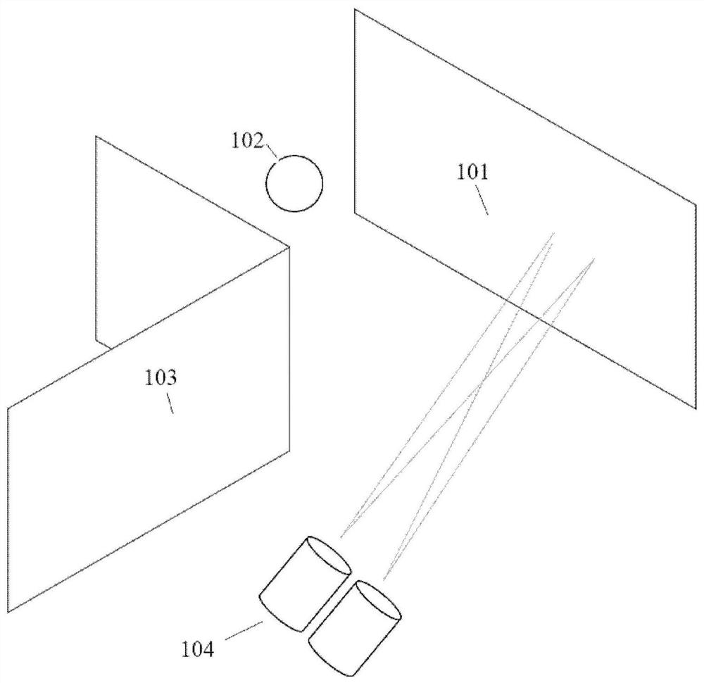
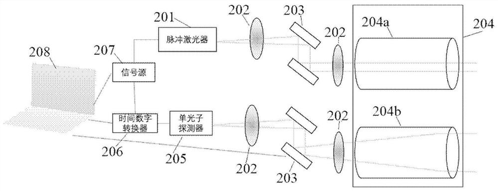
A non-vision-field imaging device comprises a near-infrared pulse laser used for emitting infrared pulse laser, a double-telescope module used for emitting the infrared pulse laser to an intermediatewall after beam expansion and collimation, and receiving the infrared pulse laser scattered back through the intermediate wall, and the double-telescope module is used for emitting the infrared pulselaser to the intermediate wall before the infrared pulse laser is scattered back by the intermediate wall.Wherein the single-photon detector is used for detecting the number of photons of infrared pulse laser scattered back through the intermediate wall, and the computer is used for recording the number of photons and the propagation time of the infrared pulse laser, counting the distribution of the number of photons in time and achieving three-dimensional reconstruction of the target on the basis of the distribution of the number of photons in time. According to the non-vision-field imaging device, a double-telescope system is adopted, coaxial receiving and transmitting of infrared pulse laser can be achieved, the difficulty of a reconstruction algorithm is lowered, and real-time trackingand positioning of a non-vision-field detection target can be achieved.

Description

technical field [0001] The present disclosure relates to the technical field of non-line-of-sight imaging, and in particular, to a non-line-of-sight imaging device and method. Background technique [0002] The 3D non-line-of-sight imaging technology based on LiDAR is a technology for 3D imaging of occluded non-line-of-sight hidden object targets. The realization process of non-line-of-sight imaging is usually to emit laser light onto the reflective surface of the intermediary wall, and use the intermediary wall to scatter the laser light into the blocked non-line-of-sight space. The scattered laser light is reflected by hidden objects in the space. , is reflected to the reflective surface of the intermediary wall again, and then is reflected by the intermediary wall to the receiving system. Finally, the computer system uses information such as the flight time of the laser to realize the hidden object target in the blocked non-visual space through an algorithm. 3D reconstruc...

Claims


Application Information

Patent Timeline
Patent Type & Authority Applications(China)
IPC IPC(8): G01S17/894G01S7/481
CPCG01S17/894G01S7/4814G01S7/4816G01S7/4817
Inventor 徐飞虎吴骋黎正平潘建伟
Owner UNIV OF SCI & TECH OF CHINA
Why Eureka
Try Eureka