Bender

A bending machine and frame technology, which is applied in the field of bending machines, can solve the problems of inability to guarantee accuracy, complex occupation of space, detachment of floating structure molds, etc., and achieve the effect of simple structure and strong practicability.

Inactive Publication Date: 2012-07-25
中船海洋与防务装备股份有限公司
View PDF8 Cites 7 Cited by
  • Summary
  • Abstract
  • Description
  • Claims
  • Application Information

AI Technical Summary

Problems solved by technology

However, the structure of the automatic deflection compensation device is generally complex and takes up a lot of space, and it is a floating structure, which may cause the hidden danger of mold detachment, so it cannot be installed under the slider, and generally can only be installed on the workbench.
Due to the limitations of the installation space and the structure of the automatic deflection compensation device, the automatic deflection compensation device cannot be installed at the lower end of the slider where the upper mold is installed, so only the automatic compensation of the deflection of the workbench can be realized. The slider can only be compensated manually, and the manual adjustment compensation The operation is cumbersome, time-consuming and labor-intensive, only subtle compensation can be performed and the accuracy cannot be guaranteed
[0007] Therefore, the current bending machines with deflection compensation function cannot realize bidirectional deflection automatic compensation, and cannot realize digital control and automatic operation.

Method used


Image

  • Bender
  • Bender
  • Bender

Examples


Embodiment Construction

[0020] The content of the present invention will be further described below with reference to the drawings and embodiments.

[0021] Such as Figure 4 , Figure 5 , Image 6 , Figure 7 , Figure 8 As shown, the present invention discloses a bending machine with a bidirectional deflection automatic compensation function, including a frame 1, a sliding block 2 and a worktable 15, four screw drive mechanisms a, b, c, d and a sliding block 2. Fixed connection, screw drive mechanisms a and d are respectively arranged at both ends of the slider 2 in the horizontal direction, screw drive mechanisms b, c are set in the middle of the slider 2, and the workbench 15 is equipped with a deflection compensation device e, the workbench The panel 16 is placed on the deflection compensation device e, and the lower die 14 is installed on the workbench panel; the screw nuts of each screw drive mechanism are fixedly installed in the bearings, and the screw nuts are fixed on the frame through the be...


PUM


Abstract

The invention discloses a bender, including a rack, a slide block and a workbench; the two ends and middle part of the slide block are connected with an independent lead screw transmission mechanism, the lead screw nut in each lead screw transmission mechanism is arranged on the rack via a bearing, the lead screw transmission mechanism is driven by a motor on the rack to rotate, the lead screw is screwed on the lead screw nut, and the bottom end is connected with the slide block; a deflection compensation device is arranged on the workbench, the workbench panel is arranged on the deflection compensation device, when in use, the deflection compensation device compensates the deformation amount of the workbench; the lead screw transmission mechanisms at the two ends stop working after driving the slide block to reach a preset position, the lead screw transmission mechanism in the middle part continues to drive the slide block some distance to compensate the elastic deformation caused when the slide block and the rack are loaded, in order to achieve bidirectional deflection compensation for the bender; the deflection compensation value of the workbench and the slide block depends on the rigidity of both the rack and the slide block and the workpiece, and digital control and automatic bidirectional deflection compensation for the bender can be achieved.

Description

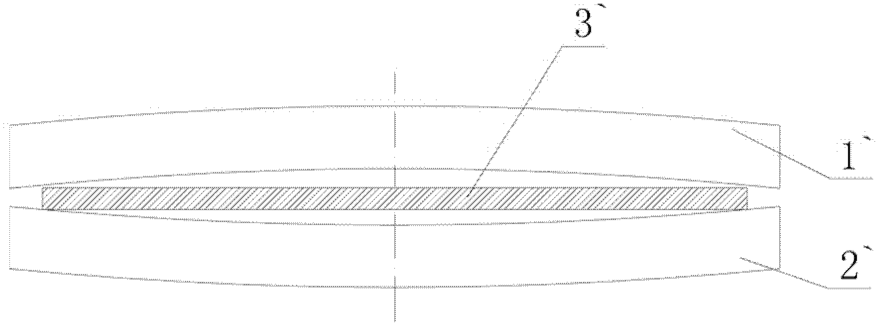
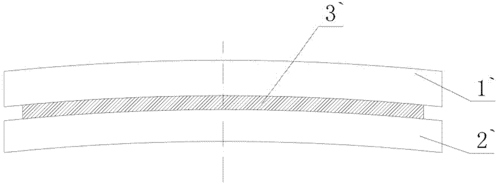
Technical field [0001] The invention relates to a bending machine, in particular to a bending machine with a bidirectional deflection automatic compensation function. Background technique [0002] Bending machine is a kind of processing machine that bends sheet metal in a straight line in a cold state. The current bending machine is generally fixed on the worktable, and the slider is synchronously driven by the hydraulic cylinders at both ends to move up and down linearly. The upper mold at the bottom of the block and the lower mold on the worktable press the workpiece into shape. [0003] The forming mold used by the bending machine is linear and long and narrow. Due to the rigidity of the frame supporting the mold, the sliding block and the table, it is inevitable that a certain degree of deflection will occur, causing the bending angle of the workpiece to be small at both ends and large in the middle. Such as figure 1 As shown, the middle of the upper mold 1` is raised upwards,...

Claims


Application Information

Patent Timeline
Patent Type & Authority Applications(China)
IPC IPC(8): B21D5/06
Inventor 麦荣枝盛少琴陈尚贵熊军闫振施理军刘德全黄琼全华太冀海俊黄翠敏林灿峰李金兰
Owner 中船海洋与防务装备股份有限公司
Why Eureka
Try Eureka