
Self-sustaining friction stir welding stirring head with irrotational lower shaft shoulder and welding method of stirring head
A friction stir welding and friction stir technology, which is used in welding equipment, non-electric welding equipment, metal processing equipment, etc., can solve the problems of low mechanical properties of welded joints, increased welding heat input, and difficulty in welding seam forming, so as to reduce welding heat. Input, reduce loads, improve the effect of weld formation
- Summary
- Abstract
- Description
- Claims
- Application Information
AI Technical Summary
Problems solved by technology
Method used
Image

Examples
specific Embodiment approach 1
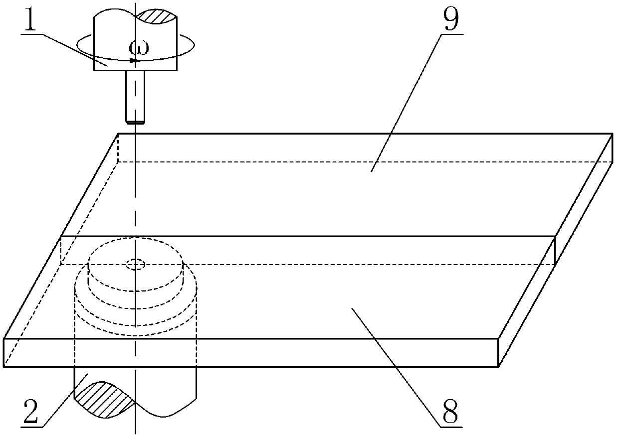
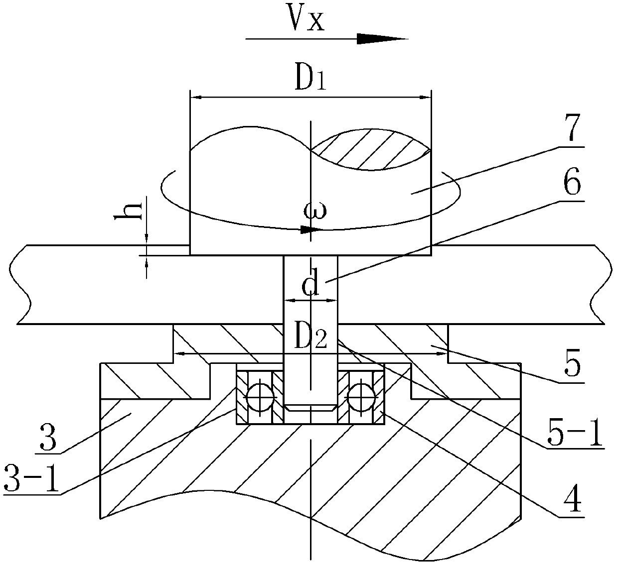
[0017] Specific implementation mode one: as Figure 1~2 As shown, a self-sustaining friction stir welding stirring head with a non-rotating lower shoulder in this embodiment, the stirring head is composed of an upper stirring head 1 and a lower stirring head 2, and the upper stirring head 1 is composed of an upper shaft The shoulder 7 and the stirring needle 6 are composed of the upper end surface of the stirring needle 6 fixed on the lower end surface of the upper shoulder 7, and the upper shoulder 7 and the stirring needle 6 are coaxially arranged, and it is characterized in that: the lower stirring The head 2 is composed of a supporting base 3, a radial positioning bearing 4 and a lower shoulder 5, the center of the upper end surface of the supporting base 3 is processed with a circular groove 3-1, and the radial positioning bearing 4 is installed on a circular In the shaped groove 3-1, the lower shoulder 5 is fixed on the upper end surface of the support base 3, and the lo...
specific Embodiment approach 2
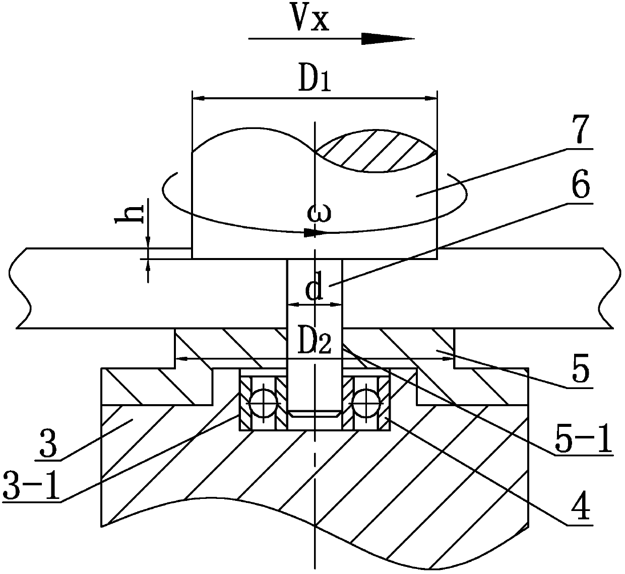
[0018] Specific implementation mode two: as figure 2 As shown, the diameter D1 of the upper shoulder 7 in this embodiment is 3 to 5 times the thickness of the workpiece to be welded, the diameter D2 of the lower shoulder 5 is 4 to 6 times the thickness of the workpiece to be welded, and the diameter d of the stirring pin 6 is 3 to 5 times the thickness of the workpiece to be welded. 1 to 2 times the thickness of the welded workpiece. With such a design, good weld seam formation can be obtained while ensuring sufficient strength of the stirring needle. Other steps are the same as in the first embodiment.
specific Embodiment approach 3
[0019] Specific implementation mode three: as figure 2 As shown, the diameter D1 of the upper shaft shoulder 7 in this embodiment is 4 times of the thickness of the workpiece to be welded, the diameter D2 of the lower shoulder 5 is 5 times of the thickness of the workpiece to be welded, and the diameter d of the stirring pin 6 is 4 times of the thickness of the workpiece to be welded. 1.5 times. With such a design, good weld seam formation can be obtained while ensuring sufficient strength of the stirring needle. Other steps are the same as in the second embodiment.
PUM
 Abstract
Description
Claims
Application Information