Self-sustaining friction stir welding stirring head with irrotational lower shaft shoulder and welding method of stirring head

A friction stir welding and stirring head technology, which is applied in welding equipment, non-electric welding equipment, metal processing equipment, etc., can solve the problems of increased welding heat input, low mechanical properties of welded joints, and difficulty in welding seam forming, so as to reduce welding heat. Input, increase bearing capacity, improve the effect of weld forming

Inactive Publication Date: 2014-08-06
HARBIN INST OF TECH
View PDF6 Cites 0 Cited by
  • Summary
  • Abstract
  • Description
  • Claims
  • Application Information

AI Technical Summary

Problems solved by technology

[0004] In order to solve the problem that the lower shoulder of the existing self-sustaining friction stir welding stirrer rotates to produce heat, the welding heat input increases, the welding seam is difficult to form and the mechanical properties of the welded joint are low, and a lower shoulder is proposed. Rotating self-contained stirring head

Method used


Image

  • Self-sustaining friction stir welding stirring head with irrotational lower shaft shoulder and welding method of stirring head
  • Self-sustaining friction stir welding stirring head with irrotational lower shaft shoulder and welding method of stirring head

Examples


specific Embodiment approach 1

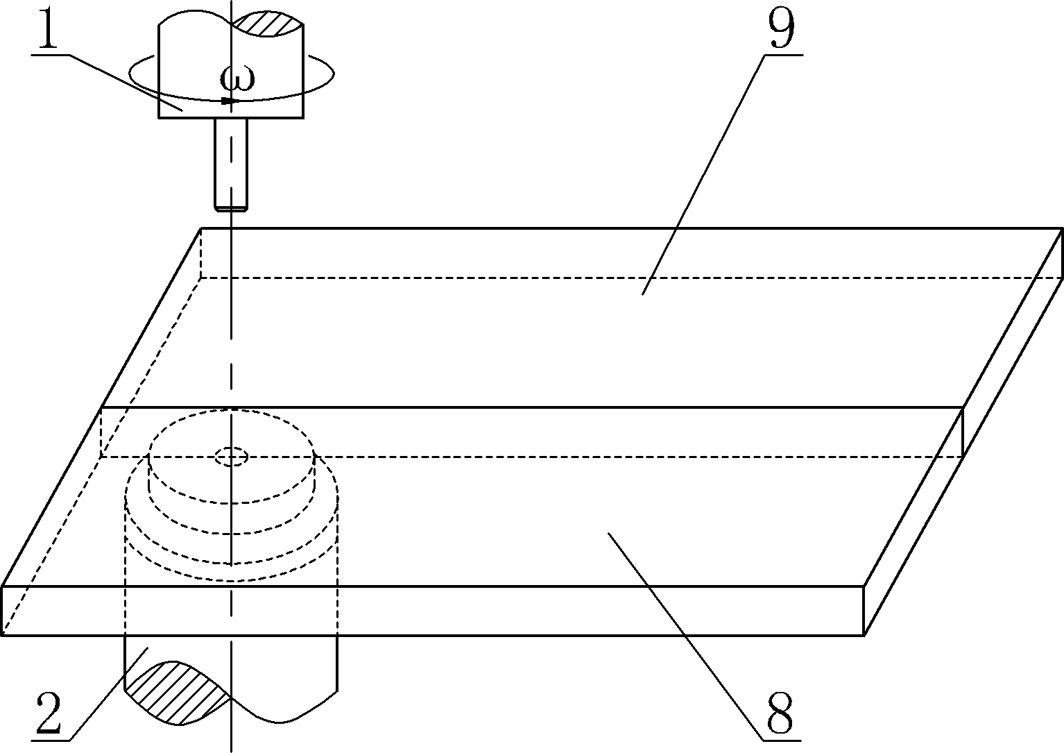
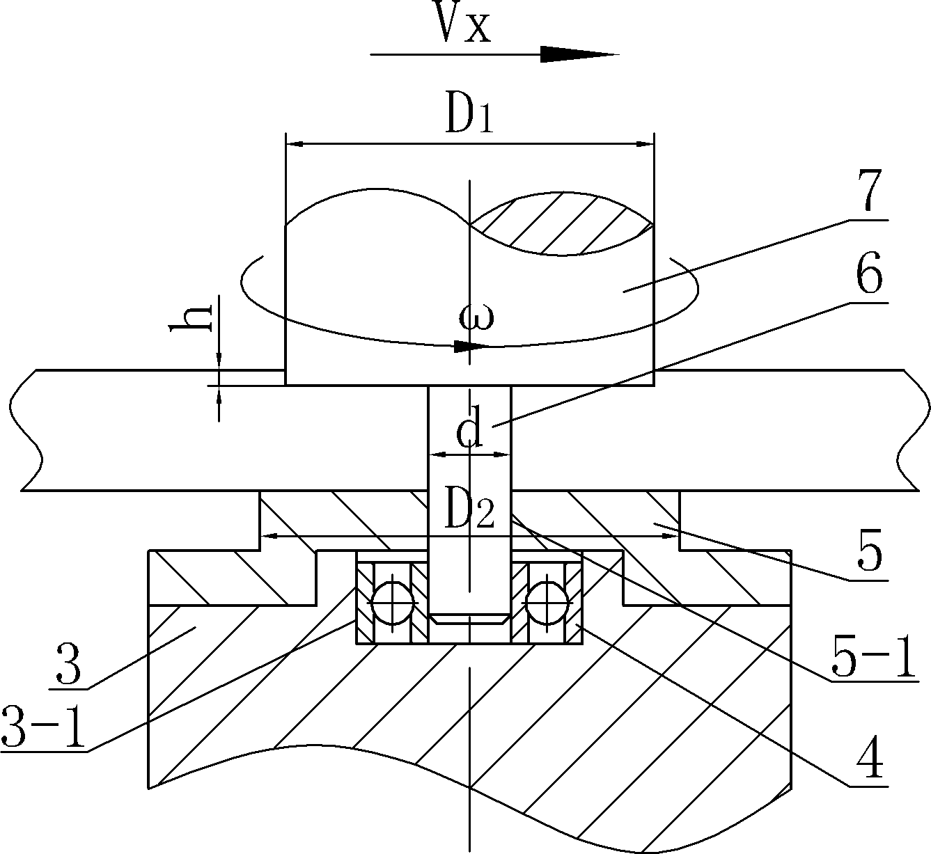
[0017] Specific implementation mode one: as Figures 1 to 2 As shown, a self-sustaining friction stir welding stirring head with a non-rotating lower shoulder in this embodiment, the stirring head is composed of an upper stirring head 1 and a lower stirring head 2, and the upper stirring head 1 is composed of an upper The shaft shoulder 7 and the stirring needle 6 are composed, the upper end surface of the stirring needle 6 is fixed on the lower end surface of the upper shoulder 7, the upper shoulder 7 and the stirring needle 6 are coaxially arranged, and it is characterized in that: the lower The stirring head 2 is composed of a supporting base 3, a radial positioning bearing 4 and a lower shaft shoulder 5, the center of the upper end surface of the supporting base 3 is processed with a circular groove 3-1, and the radial positioning bearing 4 is installed on In the circular groove 3-1, the lower shoulder 5 is fixed on the upper end surface of the support base 3, and the lowe...

specific Embodiment approach 2

[0018] Specific implementation mode two: as figure 2 As shown, the diameter D1 of the upper shoulder 7 in this embodiment is 3 to 5 times the thickness of the workpiece to be welded, the diameter D2 of the lower shoulder 5 is 4 to 6 times the thickness of the workpiece to be welded, and the diameter d of the stirring pin 6 is 3 to 5 times the thickness of the workpiece to be welded. 1 to 2 times the thickness of the welded workpiece. With such a design, good weld seam formation can be obtained while ensuring sufficient strength of the stirring needle. Other steps are the same as in the first embodiment.

specific Embodiment approach 3

[0019] Specific implementation mode three: as figure 2 As shown, the diameter D1 of the upper shaft shoulder 7 in this embodiment is 4 times of the thickness of the workpiece to be welded, the diameter D2 of the lower shoulder 5 is 5 times of the thickness of the workpiece to be welded, and the diameter d of the stirring pin 6 is 4 times of the thickness of the workpiece to be welded. 1.5 times. With such a design, good weld seam formation can be obtained while ensuring sufficient strength of the stirring needle. Other steps are the same as in the second embodiment.


PUM


Abstract

The invention relates to a stirring head, in particular to a self-sustaining friction stir welding stirring head with an irrotational lower shaft shoulder. The invention solves the problems that welding heat input is increased as a lower shaft shoulder of an existing self-sustaining friction stir welding stirring head rotates to generate heat, weld formation is difficult, and the mechanical property of a welding joint is low. An upper end surface of a stirring needle is fixed on a lower end surface of an upper shaft shoulder. The upper shaft shoulder and the stirring needle are arranged coaxially, and are characterized in that the lower stirring head is composed of a support base, a radial positioning bearing and the lower shaft shoulder, a circular groove is machined at the center of the upper end face of the support base, the radial positioning bearing is mounted in the circular groove, the lower shaft shoulder is fixedly mounted on the upper end face of the support base, and central holes are processed on the lower shaft shoulder along the longitudinal direction. In the welding process, the lower part of the stirring needle runs through the central holes and is installed on the support base through the radial positioning bearing. The diameter D2 of the lower shaft shoulder is not less than that D1 of the upper shaft shoulder. The stirring head of the invention is used for friction stir welding.

Description

technical field [0001] The invention relates to a stirring head for friction stir welding. Background technique [0002] The self-sustaining friction stir welding method is a new type of environmentally friendly solid phase connection technology derived from conventional friction stir welding. It can not only effectively avoid welding defects such as cracks and pores caused by traditional fusion welding methods, but also solve conventional friction stir welding. Welding needs a backing plate, and there may be problems such as root defects in the weld, so the self-sustaining friction stir welding method has been rapidly developed and widely used. In the above method, the stirring head is composed of a stirring pin and upper and lower shoulders. The lower shoulder acts as a backing plate for conventional friction stir welding. During welding, the lower shoulder is driven by the stirring pin to rotate and generate heat. The lower shaft The load on the shoulder is all applied t...

Claims


Application Information

Patent Timeline
Patent Type & Authority Patents(China)
IPC IPC(8): B23K20/12
Inventor 赵运强刘会杰侯军才李金全
Owner HARBIN INST OF TECH
Why Eureka
Try Eureka