Full-automatic chamfering machine

A chamfering machine, fully automatic technology, applied in the direction of metal processing machinery parts, clamping, support, etc., can solve the problems of low production efficiency, difficult to control production cost, low processing accuracy and so on

Inactive Publication Date: 2012-07-25
ZHEJIANG SHUNXIN MACHINERY
View PDF6 Cites 28 Cited by
  • Summary
  • Abstract
  • Description
  • Claims
  • Application Information

AI Technical Summary

Problems solved by technology

[0003] Aiming at the defects existing in the prior art, the object of the present invention is to provide a fully automatic chamfering machine, which solves the problem of low

Method used


Image

  • Full-automatic chamfering machine
  • Full-automatic chamfering machine
  • Full-automatic chamfering machine

Examples


Embodiment Construction

[0037] The present invention will be described in further detail below in conjunction with the accompanying drawings.

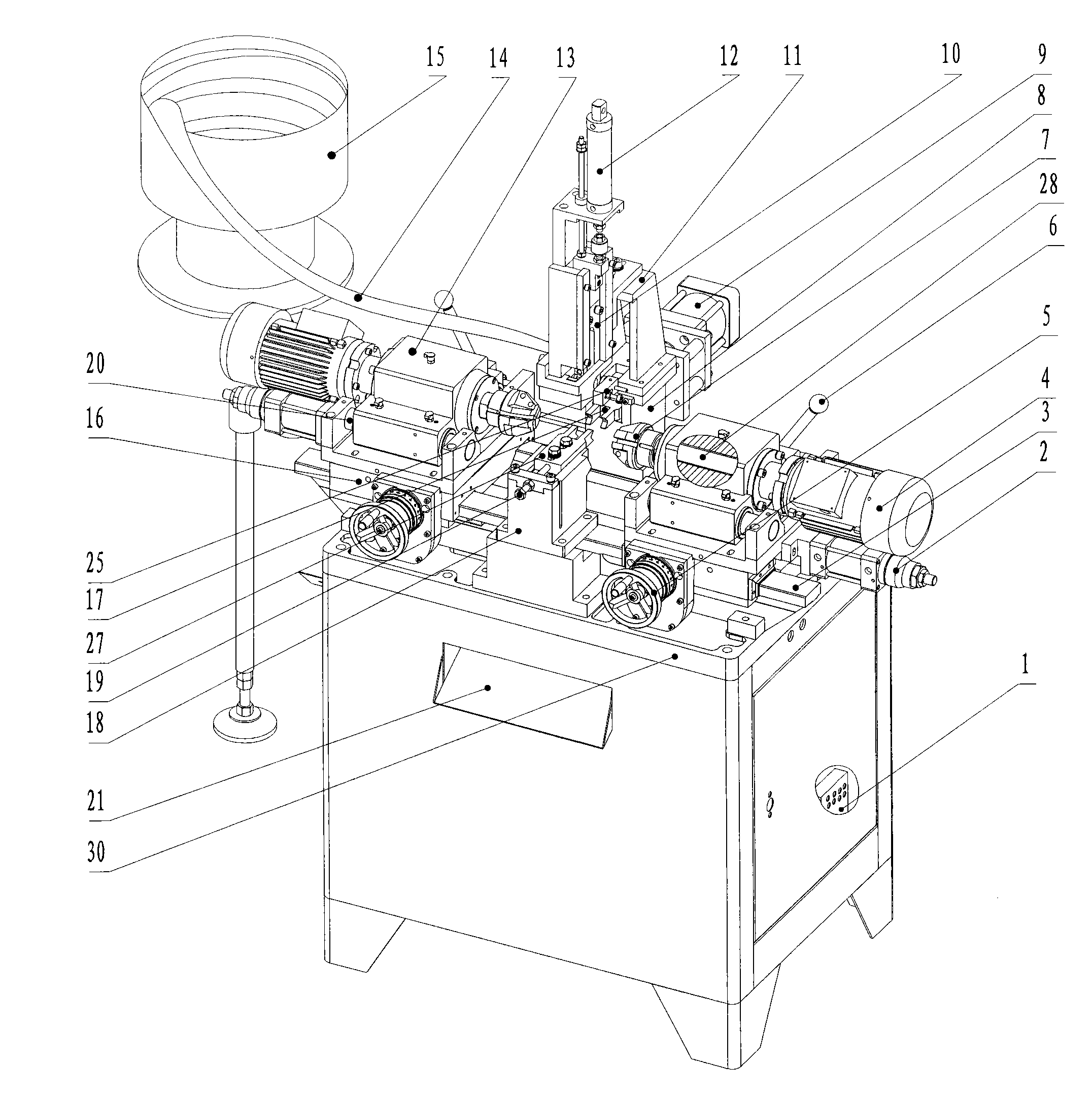
[0038] like figure 1 As shown, the fully automatic chamfering machine of the present invention includes:

[0039] A rack with a programmable logic controller (PLC) 1 inside,

[0040] The top surface of the frame is provided with a large frame base plate 30, and a feed opening is centered on the frame large base plate 30,

[0041] The rear side of the upper middle part of the large base plate 30 of the frame is provided with a feed clamp 10, the feed clamp 10 is located at the discharge end of the feed pipe 14, and the cylindrical workpiece 22 is sent to the feed clamp 10 through the feed pipe 14,

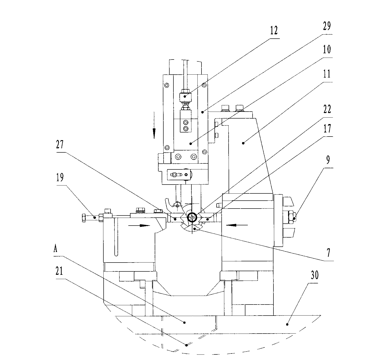
[0042] like image 3 As shown, both sides of the feed clamp 10 are provided with feed guide blocks 29 that limit its movement track, and the feed guide blocks 29 are located directly above the discharge port on the large bottom plate 30 of the frame, and are lim...


PUM


Abstract

The invention relates to a full-automatic chamfering machine, which comprises a rack that is internally provided with a programmable logic controller, wherein a large rack bottom plate is arranged on the top surface of the rack, a blanking hole is arranged in the center of the large rack bottom plate, a feeding clamp is arranged at the rear side of the middle part of the large rack bottom plate and is driven by a feeding air cylinder arranged above the feeding clamp, the feeding air cylinder is fixed on the large rack bottom plate by a trapezoid feeding base plate, a fixed clamp and a movable clamp are arranged oppositely front and back and are respectively positioned at the front side and the rear side of the blanking hole of the large rack bottom plate, a cylindrical workpiece and the large rack bottom plate are clamped by the fixed clamp and the movable clamp in parallel, the left side and the right side of the large rack bottom plate are respectively provided with a guide rail that is in parallel to the cylindrical workpiece, and a pair of workpiece machining mechanisms are respectively connected with one guide rail in a sliding way. The full-automatic chamfering machine integrates automatic feeding, material clamping, chamfering and blanking, end surface chamfering and end surface cutting are carried out on the cylindrical workpiece, and therefore, the full-automatic chamfering machine can realize the simultaneous machining of a plurality of machining stations.

Description

technical field [0001] The invention relates to a chamfering device, in particular to a fully automatic chamfering machine. Background technique [0002] The end face chamfering and cut end face of existing cylindrical workpieces (including solid cylindrical workpieces and hollow cylindrical workpieces) are usually processed on ordinary lathes. For example: taking a cylindrical water pipe (hollow) as an example, it requires two alignments and clamping to complete the processing of the inner and outer chamfers and end faces of both ends. One alignment and clamping can only process three surfaces at one end, and it requires The three stations are processed in batches, the processing precision is low, the labor intensity is high, and it is difficult to control the production cost. Contents of the invention [0003] Aiming at the defects existing in the prior art, the object of the present invention is to provide a fully automatic chamfering machine, which solves the problem ...

Claims


Application Information

Patent Timeline
IPC IPC(8): B23P23/00B23Q3/12B23Q7/00
Inventor 赵顺成张信义
Owner ZHEJIANG SHUNXIN MACHINERY
Why Eureka
Try Eureka