
A transmission mechanism of a press manipulator

A technology of conveying mechanism and manipulator, applied in the direction of presses, manufacturing tools, etc., can solve the problems of low transmission efficiency and poor stability, and achieve the effects of reducing labor intensity, improving stability, simplifying structure and cost

Active Publication Date: 2015-09-23
CHERY AUTOMOBILE CO LTD
View PDF7 Cites 0 Cited by
  • Summary
  • Abstract
  • Description
  • Claims
  • Application Information

AI Technical Summary

Problems solved by technology

[0003] The present invention designs a transmission mechanism of the manipulator of the press, which solves the problems of low transmission efficiency and poor stability in the transmission mode of the existing press materials

Method used


Image

  • A transmission mechanism of a press manipulator
  • A transmission mechanism of a press manipulator

Examples


Embodiment Construction

[0021] Below in conjunction with accompanying drawing, the present invention will be further described:

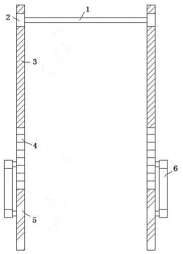
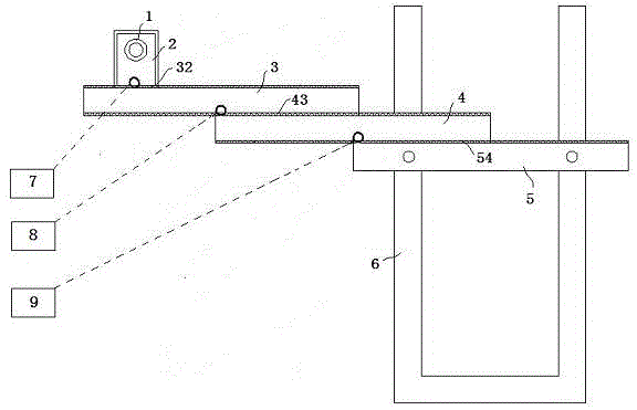
[0022] figure 1 and figure 2 It shows a transmission mechanism of a press manipulator. The manipulator is composed of a pair of transmission devices. The pair of transmission devices are arranged in parallel and fixed on the foundation of the press equipment through the base 6, but are not connected with the press. The pair of transmission devices consist of A set of manipulator transmission mechanism is equivalent to two arms fixing a crossbar 1, and the manipulator is installed on the crossbar 1. The transmission device drives the manipulator back and forth between the two presses to realize the transfer of materials between the two presses. This type of transmission can reach 15spm, which greatly improves the transmission efficiency between presses, and at the same time, the stability is further improved. In this embodiment, the manipulator adopts an end picker.

[0...


PUM


Abstract

The invention relates to a delivery mechanism for a manipulator of a press comprises a delivery device and the manipulator. The delivery device drives the manipulator to reciprocate between two presses. The delivery mechanism is characterized in that the delivery device is a three-step gear-rack climactic transmission device which comprises a driving motor set, a transverse rod (1), a first movable rod (2), a second movable rod (3), a third movable rod (4) and a fixed rod (5). The manipulator is connected to the first movable rod (2) through the transverse rod (1), relative movement of the first movable rod (2) and the second movable rod (3) is realized through a first gear-rack transmission pair (32), relative movement of the second movable rod (3) and the third movable rod (4) is realized through a second gear-rack transmission pair (43), and relative movement of the third movable rod (4) and the fixed rod (5) is realized through a third gear-rack transmission pair (54).

Description

technical field [0001] The invention relates to an automatic transmission mechanism and its method between presses, in particular to a transmission mechanism for a press manipulator. Background technique [0002] At present, the transmission methods between presses mainly include manual loading and unloading, robot loading and unloading, and single-arm manipulator loading and unloading. Manual loading and unloading means that personnel load and unload materials between presses. This method has the characteristics of low safety factor and low work efficiency; robot loading and unloading means that robots load and unload materials between presses. This method mainly considers the distance between presses, plate Factors such as material separation and mold, these factors are also the main factors affecting this mechanism, and the production efficiency will be reduced; single-arm manipulator loading and unloading means using single-arm manipulator for loading and unloading, this...

Claims


Application Information

Patent Timeline
Patent Type & Authority Patents(China)
IPC IPC(8): B30B15/30B30B15/32
Inventor 黄在荣
Owner CHERY AUTOMOBILE CO LTD
Learn More