

Anti-pricking tire
A technology for tires and carcasses, applied in tire parts, reinforcement layers of pneumatic tires, transportation and packaging, etc., can solve the problems of reducing tire service life, reducing elasticity, and poor tread puncture resistance, and extending service life. , Improve the service life and the effect of strong bearing capacity
- Summary
- Abstract
- Description
- Claims
- Application Information
AI Technical Summary
Problems solved by technology
Method used
Image

Examples
Embodiment 1
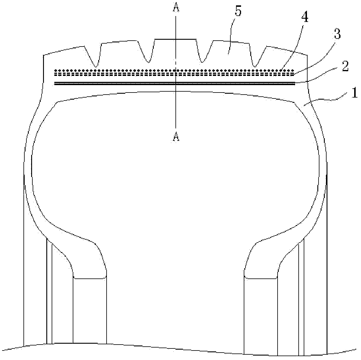
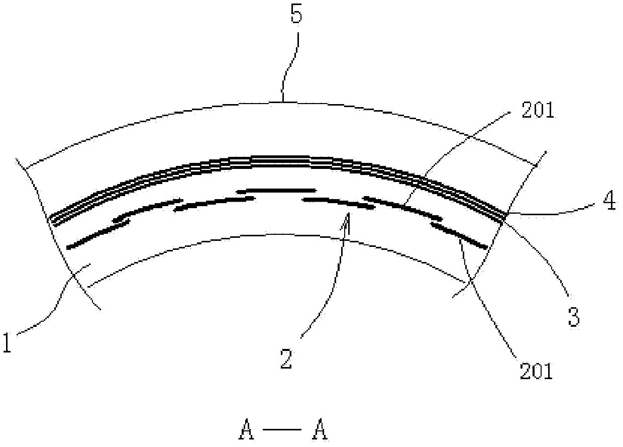
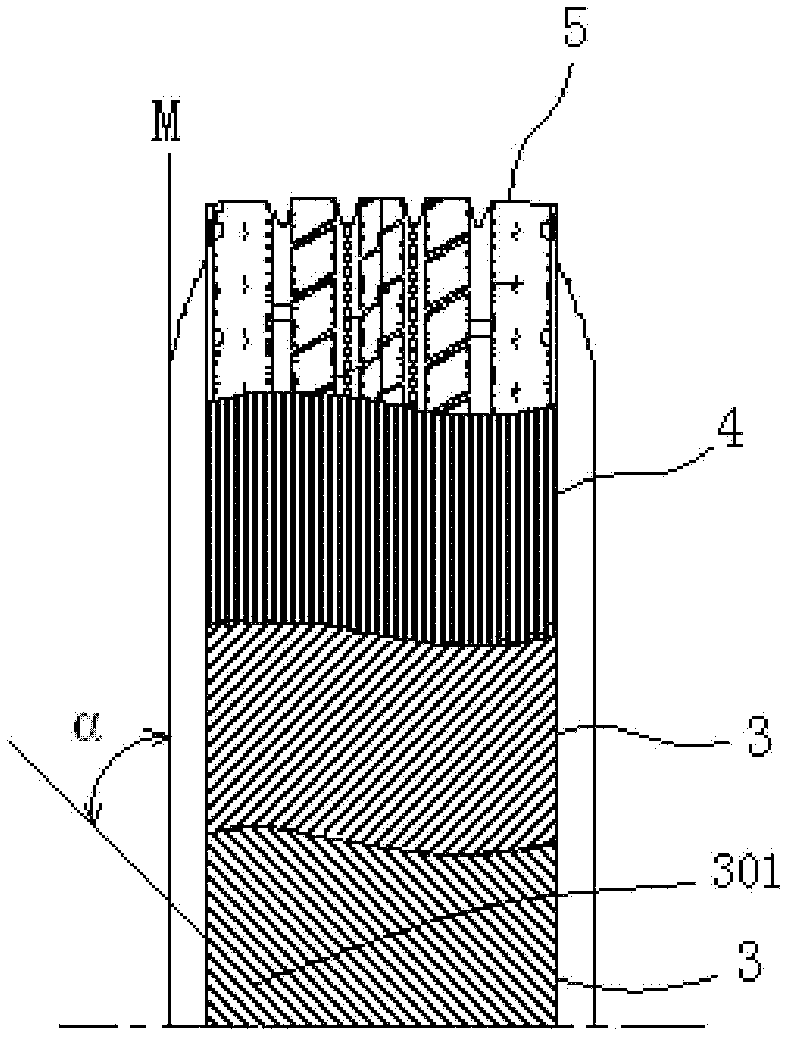
[0029] See Figure 1-Figure 3 , an anti-puncture tire, including a carcass 1 and a tread 5 vulcanized integrally with the carcass 1. Three layers of belt layers are vulcanized in the tread 5. From the outside to the inside, the first layer is formed by winding a steel wire along the direction of rotation of the tire. The spiral belt layer 4 formed, the helix angle of the spiral belt layer 4 changes with the tire diameter, the diameter of the steel wire and the size of the steel wire interval. The second layer and the third layer are diagonal belt layers 3 that cross each other; The included angle α between the steel wire 301 in the bias belt 3 and the plane M where the tire rotation direction is located is 45°-75° (see image 3 ); anti-trap ring 2 is vulcanized in the carcass 1, and anti-trap ring 2 is made up of several anti-trap sheets 201 stacked on different circumferences by two circles, and anti-trap sheet 201 is as Figure 4 , Figure 5 As shown, there are several lou...
Embodiment 2
[0032] See Figure 6 , the difference between this embodiment and implementation 1 is that the carcass 1 and the tread 5 adopt teeth and grooves to cooperate, and the teeth and grooves of the carcass 1 and the tread 5 cooperate to adopt two symmetrical curved annular teeth 501a, 501b and grooves; Such as Figure 7 As shown, the inner surface of the tread 5 is provided with two symmetrical curved ring teeth 501a, 501b, and several reinforcing ribs 502 are arranged between the two teeth. The carcass 1 is provided with the curved ring teeth 501a, 501b corresponding to the curved ring groove; such as Figure 8 As shown, curved annular teeth 101a, 101b can also be set on the carcass 1, a number of reinforcing ribs 102 are arranged between the two teeth, and curved annular grooves are correspondingly arranged on the tread 5; The diagonal belt layer 3 is used to replace the anti-piercing ring.
[0033] When the tire is inflated, the carcass 1 has no helical belt layer 4 and expand...
Embodiment 3
[0035] See Figure 9 , The carcass 1 and the tread 5 of this embodiment adopt tooth and groove cooperation, and the rest are the same as in Embodiment 1.
PUM
 Abstract
Description
Claims
Application Information