Pay-off frame for ultrathin guide line

A pay-off frame and wire technology, applied in the field of pay-off racks, can solve problems such as wire breakage, stranded wire quality and pass rate drop, breakage, etc., to achieve stable pay-off tension, not easy to break, and smooth pay-off process Effect

Active Publication Date: 2012-07-25
苏州久隆新材料科技有限公司
View PDF6 Cites 35 Cited by
  • Summary
  • Abstract
  • Description
  • Claims
  • Application Information

AI Technical Summary

Problems solved by technology

The existing pay-off racks for making stranded wires are generally controlled by a motor to pull the wires to pay out. Such ultra-fine wires with a diameter of less than 0.03 mm will inevitably break when paying out, especially when the motor starts and stops instantly, and When the pulling speed of the motor pulling the wire becomes faster or slower, due to the rapid change of the tension of the wire, it is very easy to cause wire breakage during the wire release, which will reduce the quality and pass rate of the stranded wire, and even affect the progress of production.

Method used


Image

  • Pay-off frame for ultrathin guide line
  • Pay-off frame for ultrathin guide line
  • Pay-off frame for ultrathin guide line

Examples


Embodiment 1

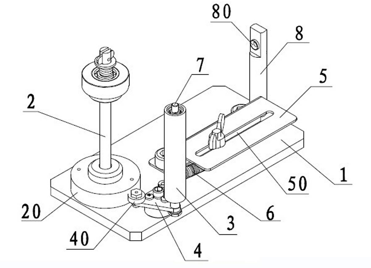
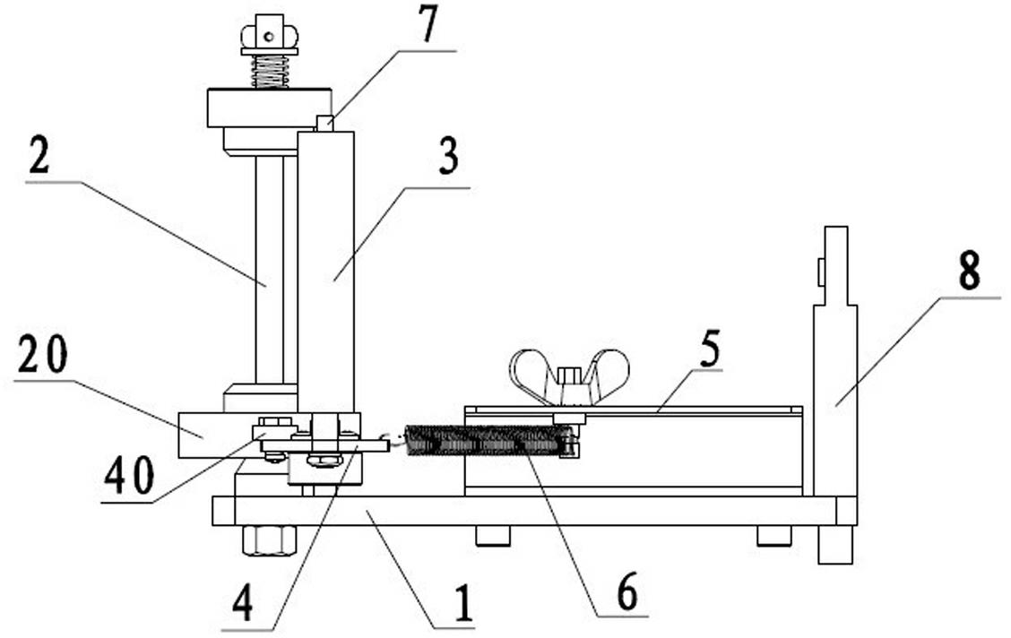
[0025] Such as Figure 1~4 As shown, a pay-off stand for ultra-fine wires includes a base 1, which is vertically arranged at one end of the base 1, and is used to cover a pay-off spindle 2 with a reel 9 wound with ultra-fine wires, a fixed shaft 7, Sleeve on the fixed shaft 7, be used for pulling the lead guide roller 3 of very fine wire when paying out, be arranged on the strut 8 on the end that is positioned at the opposite end of pay-off main shaft 2 of base 1, and be arranged on base The extension spring adjustment mechanism on the seat 1; the upper part of the pole 8 is provided with an outlet hole 80 for the ultra-fine wire to pass through.

[0026] The lower part of the pay-off main shaft 2 is provided with a rotating tray 20 that can rotate around the axial direction of the pay-off main shaft 2 and is used for supporting the pay-off reel 9 . The tension spring adjusting mechanism includes a triangular adjusting disc 4 , a fixing plate 5 arranged on one side of the...

Embodiment 2

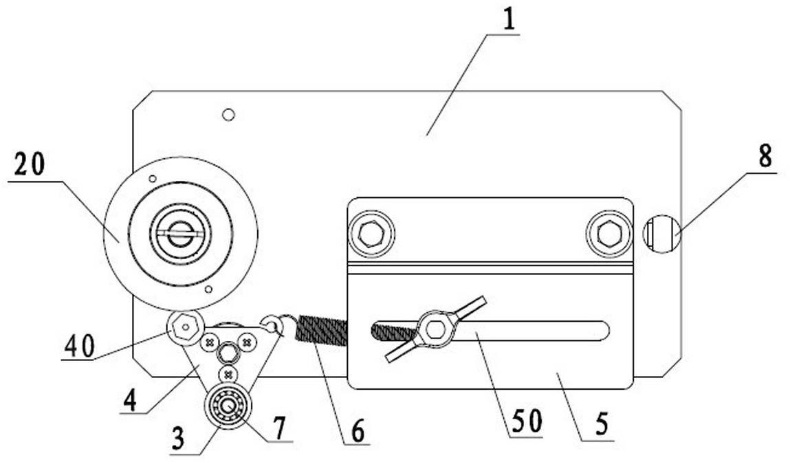
[0030] by Figure 5 The installation of the wire reel shown and the way of paying off the wire are described as follows to the working process of the pay-off stand of embodiment 1:

[0031] Set the wire reel 9 of the ultra-fine wire on the pay-off spindle 2, and hold it by the rotating tray 20. The extension spring 6 is locked at a certain position on the guide rail 50 of the fixed plate 5 and maintains a certain tension, so that the adjustment disc 4 The friction wheel 40 is against the edge of the rotating tray 20 and gives a pressure to the rotating tray 20. Since the position of the extension spring 6 on the guide rail 50 is adjustable, the pressure of the friction wheel 40 on the rotating tray 20 is also adjustable. This pressure needs to be adjusted in advance. After testing or calculation, it is obtained to keep the tension of the ultra-fine wire at the best value when paying off, so as to balance the paying off.

[0032] When unwinding, the ultra-fine wire is pu...


PUM


Abstract

The invention relates to a pay-off frame for an ultrathin guide line. The pay-off frame comprises a base, a main pay-off shaft, a traction guide roller and a tension spring adjusting mechanism, wherein a rotary tray capable of rotating axially by surrounding the main pay-off shaft is arranged at the lower part of the main pay-off shaft; the tension spring adjusting mechanism comprises an adjusting tray, a fixing plate and a tension spring connected between the adjusting tray and the fixing plate; and the adjusting tray is also provided with a friction wheel capable of rubbing and contacting the edge of the rotary tray, and the traction guide roller is arranged on the adjusting tray. When the pay-off speed is normal, the friction wheel props against the edge of the rotary tray so as to provide friction force and pressure to the rotary tray; when the pay-off speed is increased, the tension force of the ultrathin guide line on the traction guide roller is increased, so that the traction guide roller drives the adjusting tray to overcome the tension force of the tension spring, so that the moving tendency of the adjusting tray far away from the rotary tray is increased, the friction force and the pressure of the friction wheel to the rotary tray are reduced, furthermore, the pay-off speed of the ultrathin guide line is increased, the pay-off tension force falls back so as to be kept stable. According to the pay-off frame, the tension force is balanced and the line is not easy to break in the pay-off process.

Description

technical field [0001] The invention relates to cable production equipment, in particular to a pay-off frame for ultra-fine wires. Background technique [0002] With the rapid development of household appliances and electronic communication industries, electronic products such as computers and mobile phones have been widely used. Silver plating, tin plating or pure copper are often used in such electronic products and other chips such as medical precision instruments. Ultra-fine wires made of materials, their wire diameter is generally less than 0.03 mm. During the processing such as stranding of such ultra-fine wires, it is necessary to use a pay-off rack, and a plurality of ultra-fine wires are simultaneously released by the pay-off rack and twisted into twisted wires by a stranding machine. The existing pay-off racks for making stranded wires are generally controlled by a motor to pull the wires to pay out. Such ultra-fine wires with a diameter of less than 0.03 mm will ...

Claims


Application Information

Patent Timeline
Patent Type & Authority Applications(China)
IPC IPC(8): B65H49/18B65H57/06B65H57/14B65H59/38B65H59/10
Inventor 阎加军徐向东
Owner 苏州久隆新材料科技有限公司
Why Eureka
Try Eureka