
Electromagnetic fan clutch

An electromagnetic fan and clutch technology, applied in clutches, magnetic drive clutches, non-mechanical drive clutches, etc., can solve the problems of large volume, large wear of matching parts, and distance from the center of gravity, etc., and achieve compact overall structure, compact structure, and reduced wear. Effect

Active Publication Date: 2012-07-25
LONGKOU ZHONGYU AUTOMOBILE FAN CLUTCH
View PDF8 Cites 8 Cited by
  • Summary
  • Abstract
  • Description
  • Claims
  • Application Information

AI Technical Summary

Problems solved by technology

[0002] In the prior art, fan clutches used for heat dissipation of automobile engines include silicon oil type and electromagnetic type. Easy to fail; the electromagnetic clutch is electronically controlled and can usually be divided into multi-speed speed regulation. It is more fuel-efficient than ordinary fans and more stable and reliable than silicon oil fan clutches. Therefore, it is more and more applied to the heat dissipation of automobile engines.
[0003] In the prior art, the power of the electromagnetic fan clutch is transmitted from back to front to the fan fixed disk at the free end of the front to drive the fan to rotate. The volume in the axial direction is relatively large, and the center of gravity is far away from the fixed position at the rear end. The fan clutch is running The process is not stable enough, and the wear of each matching part is relatively large
[0004] In addition, in the prior art, the heat dissipation fan of the electromagnetic fan clutch is installed at the front end of the electromagnetic clutch, while the heat dissipation fan of the silicone oil fan clutch is located at the rear end of the clutch. If you want to replace the silicon oil fan clutch with an electromagnetic fan clutch, the installation position and Due to the limitation of the distance, it is necessary to change the position and structure of the engine, which brings great inconvenience to the user and is not conducive to the seamless switching between the electromagnetic fan clutch and the silicon oil fan clutch

Method used


Image

  • Electromagnetic fan clutch
  • Electromagnetic fan clutch
  • Electromagnetic fan clutch

Examples


Embodiment Construction

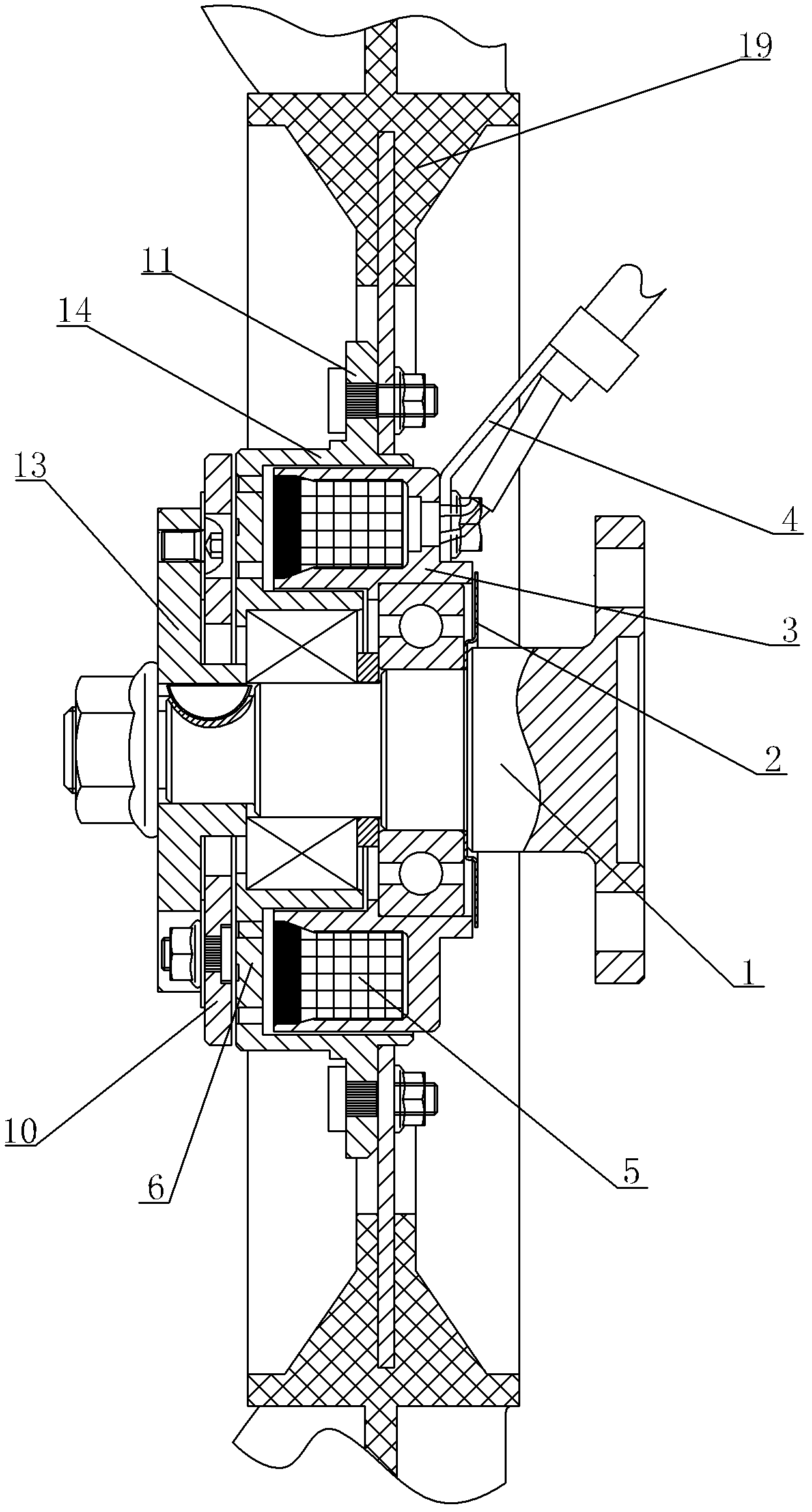
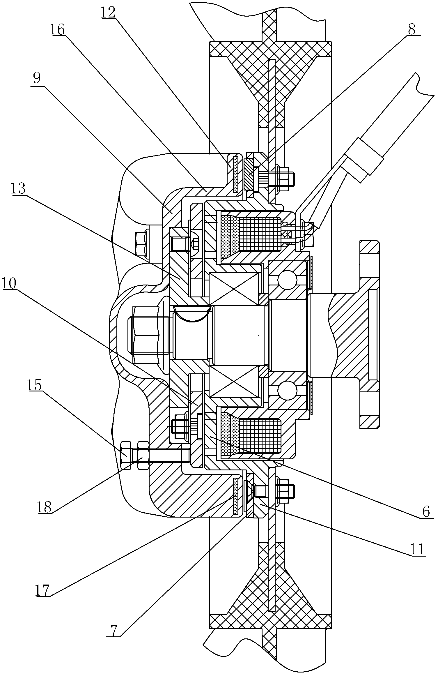
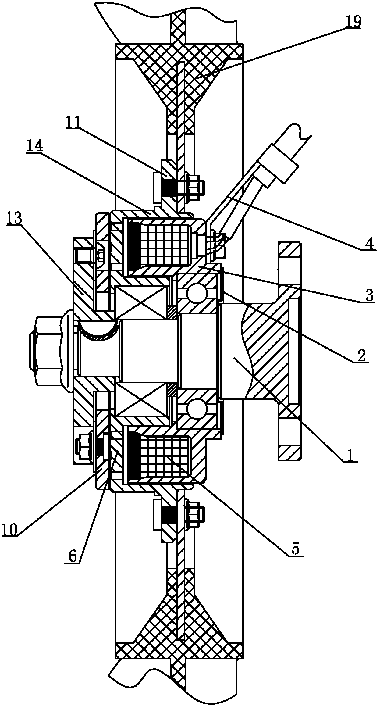
[0018] Such as figure 1 As shown, the electromagnetic fan clutch of the present invention includes a rotating main shaft 1, an electromagnet core 3 with a coil 5 embedded therein, a driven disc 6 that can rotate around the main shaft 1, and a driven disk that can rotate around the main shaft 1. The driving disc 13 that rotates with the main shaft 1 is provided with a suction disc 10 that can move in the axial direction between the driving disc 13 and the driven disc 6 , and the suction disc 10 and the driving disc 13 are connected by an elastic sheet.

[0019] The outer circumferential end surface of the driven disc 6 is axially provided with a first extension 14 toward the direction of the electromagnet core 3, the first extension 14 is radially located outside the electromagnet core 3, and the first extension 14 is on the outer wall near the free end A first skirt 11 is provided, and the first skirt 11 is perpendicular to the outer wall of the first extension 14 , and a fan ...


PUM


Abstract

The invention relates to an electromagnetic fan clutch, which is used for dissipating heat of an automobile engine and aims to be compact in structure and more stable in running. The electromagnetic fan clutch comprises a rotary spindle, electromagnet cores with embedded coils, a driven plate and a driving plate, wherein the electromagnet cores are sequentially sleeved from a support end to a free end along the axial direction of the spindle, the driven plate can rotate around the spindle, the driving plate can rotate along with the spindle, and a sucking plate capable of axially moving is disposed between the driving plate and the driven plate and is connected with the driving plate by an elastic sheet.

Description

technical field [0001] The invention relates to an electromagnetic fan clutch used for heat dissipation of an automobile engine. Background technique [0002] In the prior art, fan clutches used for heat dissipation of automobile engines include silicon oil type and electromagnetic type. It is easy to fail; the electromagnetic clutch is electronically controlled and can usually be divided into multi-speed adjustments. It is more fuel-efficient than ordinary fans and more stable and reliable than silicon oil fan clutches. Therefore, it is more and more applied to the heat dissipation of automobile engines. [0003] In the prior art, the power of the electromagnetic fan clutch is transmitted from back to front to the fan fixed disk at the free end of the front to drive the fan to rotate. The volume in the axial direction is relatively large, and the center of gravity is far away from the fixed position at the rear end. The fan clutch is running The process is not stable enoug...

Claims


Application Information

Patent Timeline
Patent Type & Authority Applications(China)
IPC IPC(8): F01P7/12F16D27/02F16D27/14
Inventor 王兆宇邢子义刘中银
Owner LONGKOU ZHONGYU AUTOMOBILE FAN CLUTCH
Learn More