
Method and device for implementation of supersonic runner

A supersonic flow, flow channel technology, applied in the direction of fluid flow, mechanical equipment, etc., can solve the problem of single compression characteristics of a single reference flow field, unable to ensure the matching of expansion and compression waves in rectangular pipes and circular pipes at the same time, to eliminate Expansion and compression waves, design flexibility, uniformity of results

Active Publication Date: 2012-07-25
NAT UNIV OF DEFENSE TECH
View PDF4 Cites 18 Cited by
  • Summary
  • Abstract
  • Description
  • Claims
  • Application Information

AI Technical Summary

Problems solved by technology

[0009] The present invention provides a method and device for realizing a supersonic flow channel to solve the problem caused by the single compression characteristic of a single reference flow field in the related art that cannot simultaneously ensure the matching of expansion and compression waves in rectangular pipes and circular pipes

Method used


Image

  • Method and device for implementation of supersonic runner
  • Method and device for implementation of supersonic runner
  • Method and device for implementation of supersonic runner

Examples


Embodiment 1

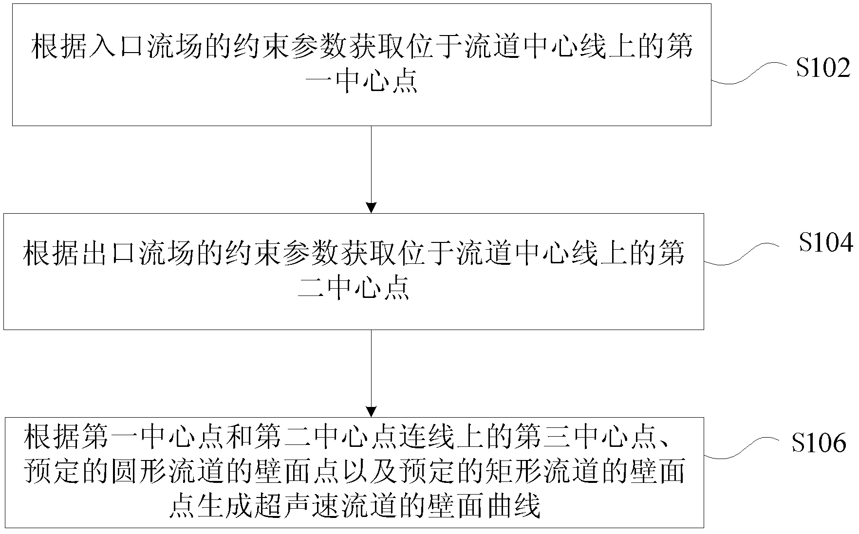
[0033] The invention provides a method for realizing a supersonic flow channel, such as figure 1 As shown, the method includes:

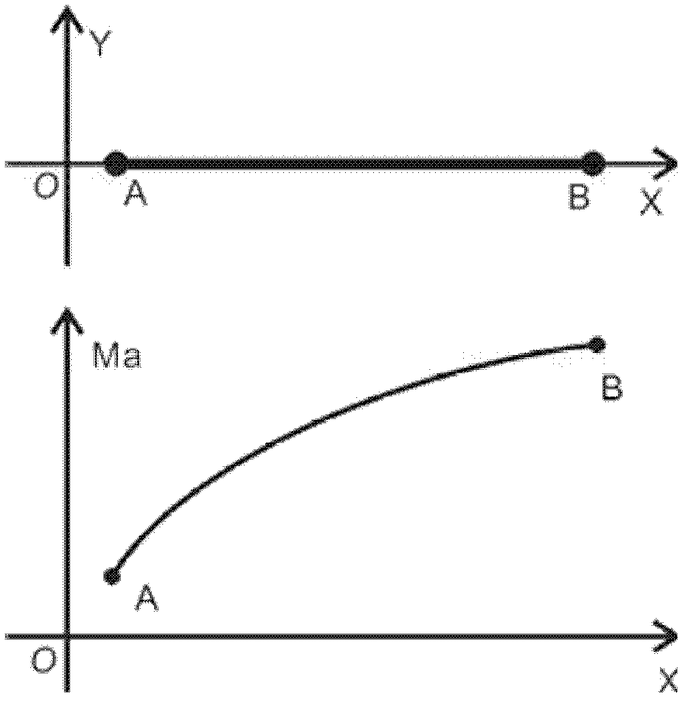
[0034] S102. Obtain a first center point located on the centerline of the flow channel according to the constraint parameters of the inlet flow field;

[0035] S104. Obtain a second center point located on the centerline of the flow channel according to the constraint parameters of the outlet flow field;

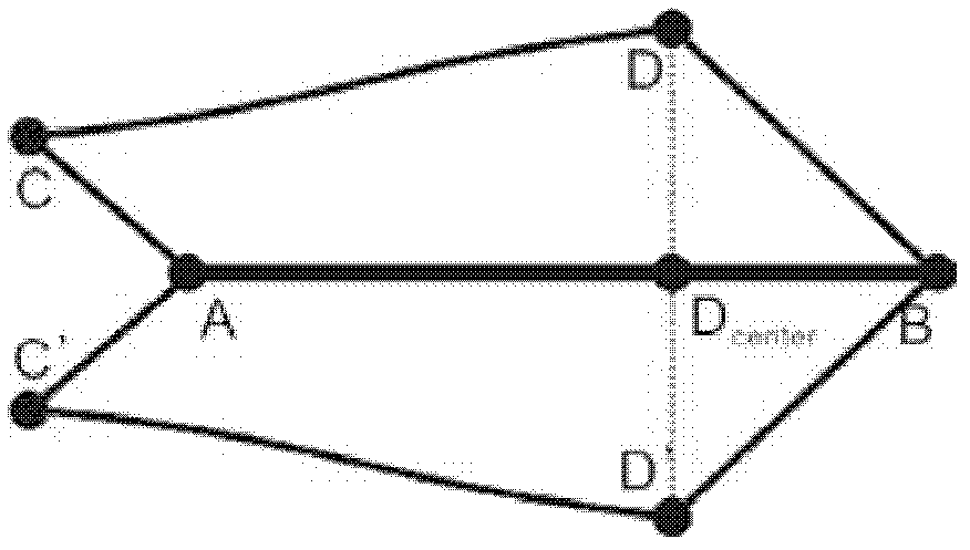
[0036] S106. Generate a wall surface curve of the supersonic flow channel according to the third center point on the line connecting the first center point and the second center point, predetermined wall points of the circular flow channel, and predetermined wall points of the rectangular flow channel.

[0037] In the above embodiment, according to the constraints of the inlet flow field and the outlet flow field, two reference flow fields are designed by the characteristic line method, and the wall curve of the supersonic flow channel is generated...

Embodiment 2

[0077] The present invention also provides a device for realizing a supersonic flow channel, such as Figure 8 As shown, the device includes: a first acquisition unit 802, used to acquire the first center point located on the centerline of the flow channel according to the constraint parameters of the inlet flow field; a second acquisition unit 804, used to acquire Obtain the second center point on the center line of the flow channel; the generation unit 806 is configured to use the third center point on the line between the first center point and the second center point, the predetermined wall point of the circular flow channel, and the predetermined Wall points for a rectangular channel generate a wall curve for a supersonic channel.

[0078] In the present invention, according to the constraints of the inlet flow field and the outlet flow field, two reference flow fields are designed by the characteristic line method, and the wall curve of the supersonic flow channel is gen...


PUM


Abstract

The invention discloses a method and a device for implementation of a supersonic runner. The method includes: acquiring a first center point on the center line of the runner according to constraint parameters of an entrance flow field; acquiring a second center point on the center line of the runner according to constraint parameters of an exit flow field; and generating a wall face curve of the supersonic runner according to a third center line on the ligature of the first center line and the second center line, preset wall face points of a circular runner and preset wall face points of a rectangular runner. The problem that the single compression characteristic of a single standard flow field in correlation technique cannot simultaneously guarantee match of expansion waves and compression waves in the rectangular pipeline and the circular pipeline, and the design of the supersonic runner with inner runner section changed from circular to rectangular is more flexible.

Description

technical field [0001] The invention relates to the field of aerodynamics, in particular to a method and device for realizing a supersonic flow channel. Background technique [0002] Supersonic flow channels, such as nozzles, inlets, isolation sections, turning sections, etc., are often used in wind tunnels and high-speed aircraft. With the development of modern aerodynamics, people have higher and higher requirements for the design of supersonic flow channels. In order to provide a better flow field environment for the aerodynamic and structural design of supersonic wind tunnels and aircraft, a supersonic flow channel whose inner flow channel cross-section changes from circular to rectangular or from rectangular to circular is often required. [0003] In the related art, there is no method for realizing the supersonic flow channel in which the cross section of the inner channel changes from circular to rectangular or from rectangular to circular based on aerodynamic princi...

Claims


Application Information

Patent Timeline
IPC IPC(8): F15D1/02
Inventor 赵玉新王振国
Owner NAT UNIV OF DEFENSE TECH
Learn More