Light emitting diode (LED) lamp

A technology of LED lights and LED light sources, applied in the field of lighting, can solve the problems of high production cost, high application of aluminum raw materials, and difficulty in improving heat dissipation efficiency, and achieve the effect of improving heat dissipation efficiency and reducing thermal resistance coefficient

Inactive Publication Date: 2012-07-25
李翘英
View PDF2 Cites 5 Cited by
  • Summary
  • Abstract
  • Description
  • Claims
  • Application Information

AI Technical Summary

Problems solved by technology

In order to increase the heat dissipation area, the radiator is generally integrally formed with aluminum profiles. Although this structure can improve heat dissipation to a certain extent, the fins in this structure are integrally formed by aluminum extrusion. Due to the limitation of the processing technology of aluminum extrusion The surface area of ​​the fins has reached the upper limit of the technology, and it is difficult to improve the heat dissipation efficiency; in addition, because the aluminum substrate and the heat sink are combined by two independent individuals through screws, there will be a huge gap between the two due to independent combination. thermal resistance, which greatly reduces the heat dissipation effect of the radiator and affects the service life of the LED light source. In addition, due to the process of aluminum substrate and aluminum extruded radiator, the application of aluminum raw materials is high, and the production cost is expensive. The extent hinders the development of LED lighting business

Method used


Image

  • Light emitting diode (LED) lamp
  • Light emitting diode (LED) lamp
  • Light emitting diode (LED) lamp

Examples


Embodiment Construction

[0029] The structure of the present invention will be described in detail below with specific embodiments in conjunction with the accompanying drawings.

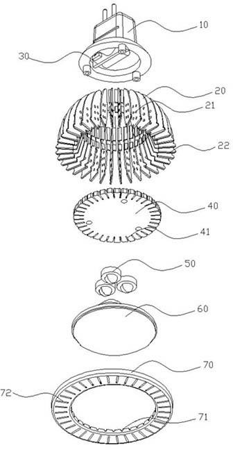
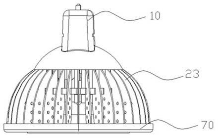
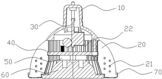
[0030] refer to figure 1 and figure 2 As shown, an LED lamp provided by the present invention includes a lamp base plastic part 10 , a driver 30 , a substrate radiator 23 , an LED light source 50 , a light source lens 60 and a cover sheet 70 . The integrated substrate radiator 23 composed of heat dissipation fins 20 and aluminum substrate 40 is a bowl-shaped structure approximately semi-spherical, with a hollow accommodation space inside. The plastic part 10 is located at the bottom of the base radiator 23: the driver 30 is located at the plastic In the accommodating space of the component 10, the LED light source 5 is fixed on the upper part of the substrate heat sink 23, and is electrically connected with the driver 30, and emits light under the control of the driver 30, and the emitted light beam is converged and refrac...


PUM


Abstract

The invention discloses a light emitting diode (LED) lamp, which comprises a lamp holder plastic part, an aluminum substrate radiator, a driver, an LED light source, and a light source lens. The plastic part is arranged at the bottom of the substrate radiator. The driver is fixed in the substrate radiator and the plastic part. The LED light source is arranged on the substrate radiator, and is electrically connected with the driver. Light beams generated by the light source after electrifying is converged and refracted through the light source lens. In the invention, the aluminum substrate radiator is a heat dissipation structure formed by an aluminum substrate and a plurality of heat dissipation fins, which reduces heat resistivity of the radiator, and simultaneously lowers the consumption of aluminum raw material due to simple structure, to really achieve effects of energy saving and environmental friendliness.

Description

technical field [0001] The invention belongs to the field of lighting, in particular to an LED lamp with a simplified structure. Background technique [0002] Currently common LED lamps include plastic parts, drivers, heat sinks, aluminum substrates inside the heat sink, LED light sources, and lenses. The plastic part is located at the bottom of the radiator. The radiator is generally bowl-shaped. The aluminum substrate is fixed in the accommodation space of the radiator, while the LED light source is fixed on the aluminum substrate and electrically connected to the driver. The lens is installed at the opening of the radiator. At the place, the light emitted by the LED light source is converged and irradiated to improve the lighting brightness. [0003] It is well known that LED lamps will generate a lot of heat in actual use, which will affect the service life of LED light sources. Therefore, how to solve the problem of heat dissipation is a research direction that the ind...

Claims


Application Information

Patent Timeline
Patent Type & Authority Applications(China)
IPC IPC(8): F21S2/00F21V29/00F21V17/10F21Y101/02F21K9/23F21V29/70F21V29/77F21V29/83F21Y115/10
Inventor 李翘英
Owner 李翘英
Why Eureka
Try Eureka