Edge-lit backlight module and liquid crystal display device with same

A backlight module and side-light technology, applied in lighting devices, fixed lighting devices, components of lighting devices, etc., can solve the problems of broken and separated wires and connectors, complicated fixing structures, and poor display screens of liquid crystal display devices, etc. , to improve the display quality, simplify the cable management structure, and save the effect of sticking tape

Inactive Publication Date: 2012-07-25
DARWIN PRECISIONS SUZHOU CORP
View PDF5 Cites 2 Cited by
  • Summary
  • Abstract
  • Description
  • Claims
  • Application Information

AI Technical Summary

Problems solved by technology

[0005] It can be seen from this that the wire management and fixing structure of the edge-lit backlight module in the prior art is relatively complicated, and the manual operation is cumbersome. Broken and separated from the connector, resulting in product scrapping, even rework is time-consuming
[0006] In the prior art, in order to fix the LED light bar and the heat sink together, the common practice is to set a plurality of hole structures on the circuit board of the LED light bar, and the positions of the hole structures are two adjacent light-emitting diodes. Set screw holes at the corresponding positions of the heat sink, and then use screws to pass through the hole structure and the screw holes to fix the LED light bar and the heat sink together. The display screen of the display device is defective

Method used


Image

  • Edge-lit backlight module and liquid crystal display device with same
  • Edge-lit backlight module and liquid crystal display device with same
  • Edge-lit backlight module and liquid crystal display device with same

Examples


Embodiment Construction

[0023] In order to have a further understanding of the purpose, structure, features, and functions of the present invention, the following detailed descriptions are provided in conjunction with the embodiments.

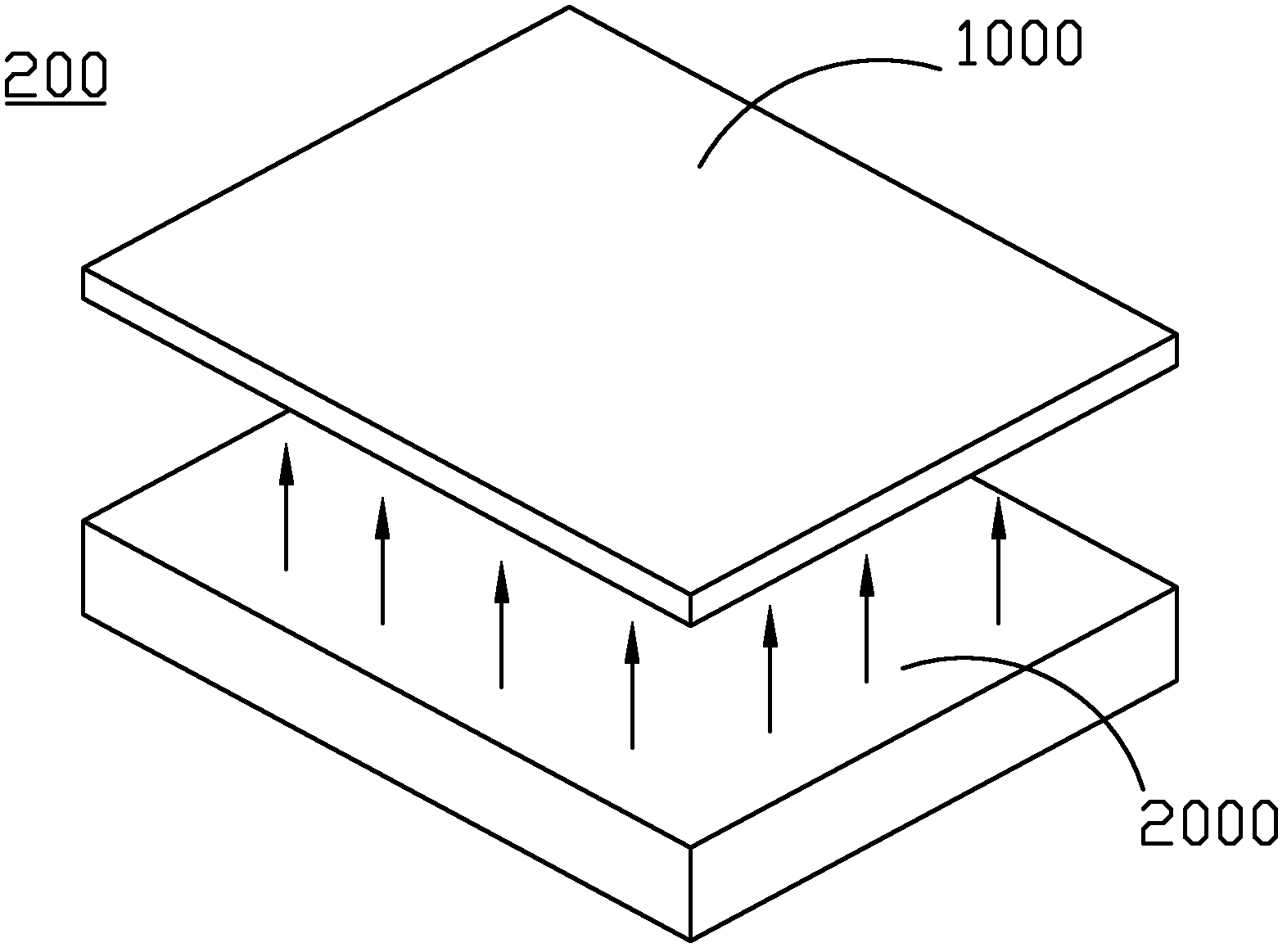
[0024] figure 2 It is a three-dimensional exploded schematic diagram of a liquid crystal display device 200 disclosed in an embodiment of the present invention. The liquid crystal display device 200 includes a liquid crystal display panel 1000 and an edge-lit backlight module 2000, wherein the liquid crystal display panel 1000 and the edge-lit backlight module The modules 2000 are stacked together, and the light is emitted from the side-light backlight module 2000 and then enters the liquid crystal display panel 1000 .

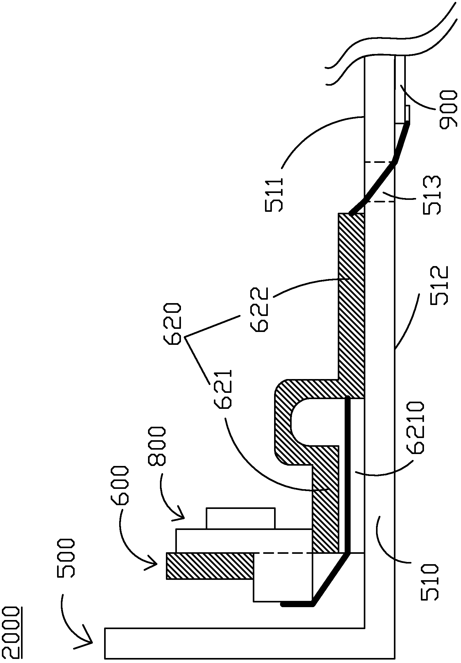
[0025] image 3 It is a partial cross-sectional view of the side of an edge-lit backlight module 2000 according to an embodiment of the present invention, Figure 4 It is a three-dimensional schematic diagram of some areas of the edge-lit backlight...


PUM


Abstract

The invention discloses an edge-lit backlight module and a liquid crystal display device with the same. The backlight module comprises a back plate, a radiating plate and at least one light emitting diode strip. A bottom plate of the back plate is provided with a first surface, a second surface and a first through hole. The radiating plate is disposed on the first surface. The lateral edge of the radiating plate is provided with a first opening. The bottom edge of the radiating plate comprises a bent part and a horizontal part, the bent part and the first surface form a first containing space, the horizontal part is mutually abutted to the first surface, and a first through channel is reserved on the horizontal part. Each light emitting diode strip comprises a circuit board, a plurality of light emitting diodes and a first connector. A wire connected to the first connector sequentially passes through the first containing space, the first through channel and the first through hole and passes from the first surface of the bottom plate to the second surface of the bottom plate. Therefore, wire arrangement and wire fixing structures in the prior art are improved.

Description

technical field [0001] The invention relates to a backlight module, in particular to a side-light backlight module and a liquid crystal display device using the side-light backlight module. Background technique [0002] With the continuous development of liquid crystal display technology, liquid crystal display products have been widely used in various fields of life. However, the liquid crystal itself does not emit light, and a light source needs to continuously provide light to the liquid crystal display screen to realize image display. In liquid crystal display products, a backlight module is usually selected to provide light. [0003] The backlight modules commonly used in the prior art are divided into side-light backlight modules and direct-light backlight modules according to the position of the light source. The advantage of the side-light backlight module is that it can reduce the overall thickness of the liquid crystal display device. Optical backlight modules are...

Claims


Application Information

Patent Timeline
IPC IPC(8): F21S8/00F21V29/00F21V17/12G02F1/13357F21Y101/02F21V29/70
Inventor 和雪芹
Owner DARWIN PRECISIONS SUZHOU CORP
Why Eureka
Try Eureka