Insulation structure of leading-out electrode/leading-out support rod of heater of high-temperature furnace

A technology of extracting electrodes and insulating structures, applied in lighting and heating equipment, ohmic resistance heating parts, furnaces, etc., to achieve the effect of saving replacement costs, easy implementation, and good insulation effect

Inactive Publication Date: 2012-07-25
苏州先端稀有金属有限公司
View PDF3 Cites 4 Cited by
  • Summary
  • Abstract
  • Description
  • Claims
  • Application Information

AI Technical Summary

Problems solved by technology

[0002] In the high temperature furnace, the heater and the furnace body are usually positioned and fixed by means of lead-out electrodes or lead-out support rods passing through the insulation screen, and the furnace body and the furnace body are required to Heaters need to be insulated, traditional technology (such as attached Figure 1 and attached Figure 2), insulation The structure is set between the insulation screen and the heater. The insulation mechanism is an Al 2 O 3 ceramic cylinder with a stepped hole in the center. After passing through the Al 2 O 3 ceramic cylinder and the insulation screen, it is fixed on the furnace body; a pin with a head protrudes from the inside of the heater and is connected to the insulating cylinder , the pin is fixedly connected to the Al 2 O 3 ceramic insulating cylinder through the positioning pin arranged along the diameter direction, and since the insulating circular structure is located between the insulation screen and the heater During the working process of the furnace, the temperature in this area is quite high, which makes the insulation performance of Al 2 O 3 ceramics invalid, and the temperature of the furnace will not rise, although tungsten Wire mesh heaters can solve this problem, but because tungsten wire mesh is difficult to process large diameters, and it cannot be applied to horizontal furnaces, which limits the temperature of large high-temperature furnaces

Method used


Image

  • Insulation structure of leading-out electrode/leading-out support rod of heater of high-temperature furnace
  • Insulation structure of leading-out electrode/leading-out support rod of heater of high-temperature furnace
  • Insulation structure of leading-out electrode/leading-out support rod of heater of high-temperature furnace

Examples


Embodiment Construction

[0016] Below in conjunction with specific embodiment technical scheme of the present invention is described in detail as follows:

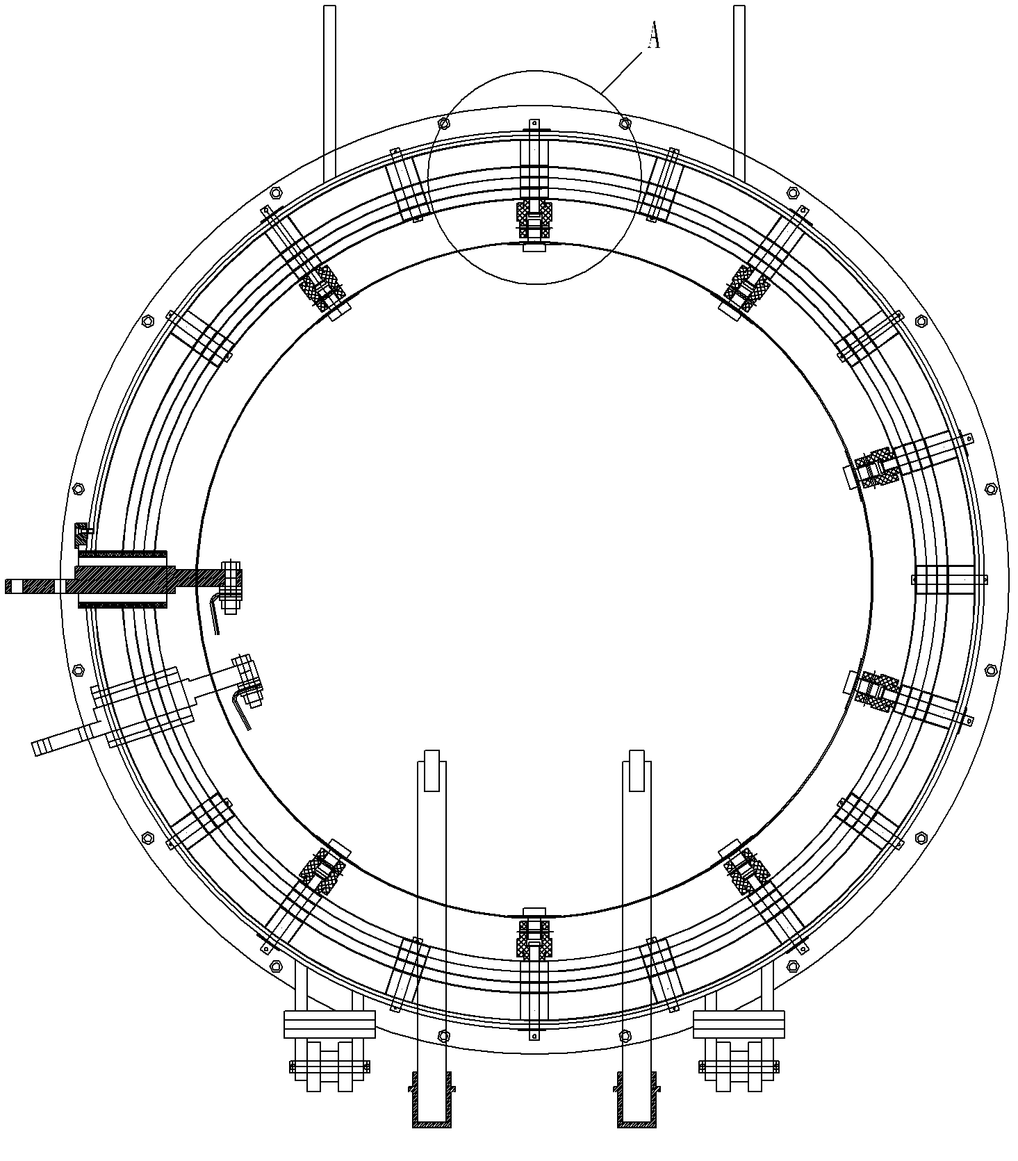
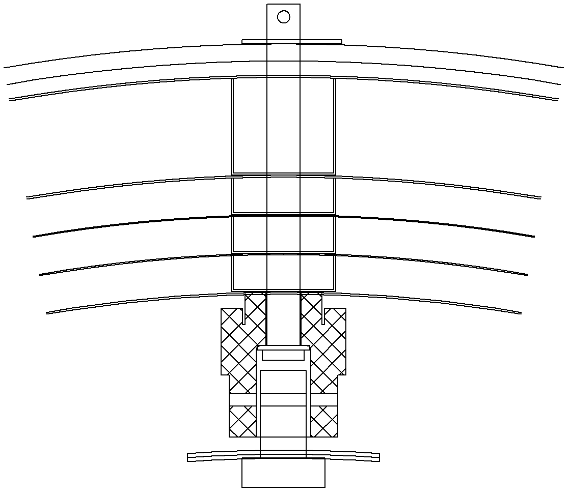
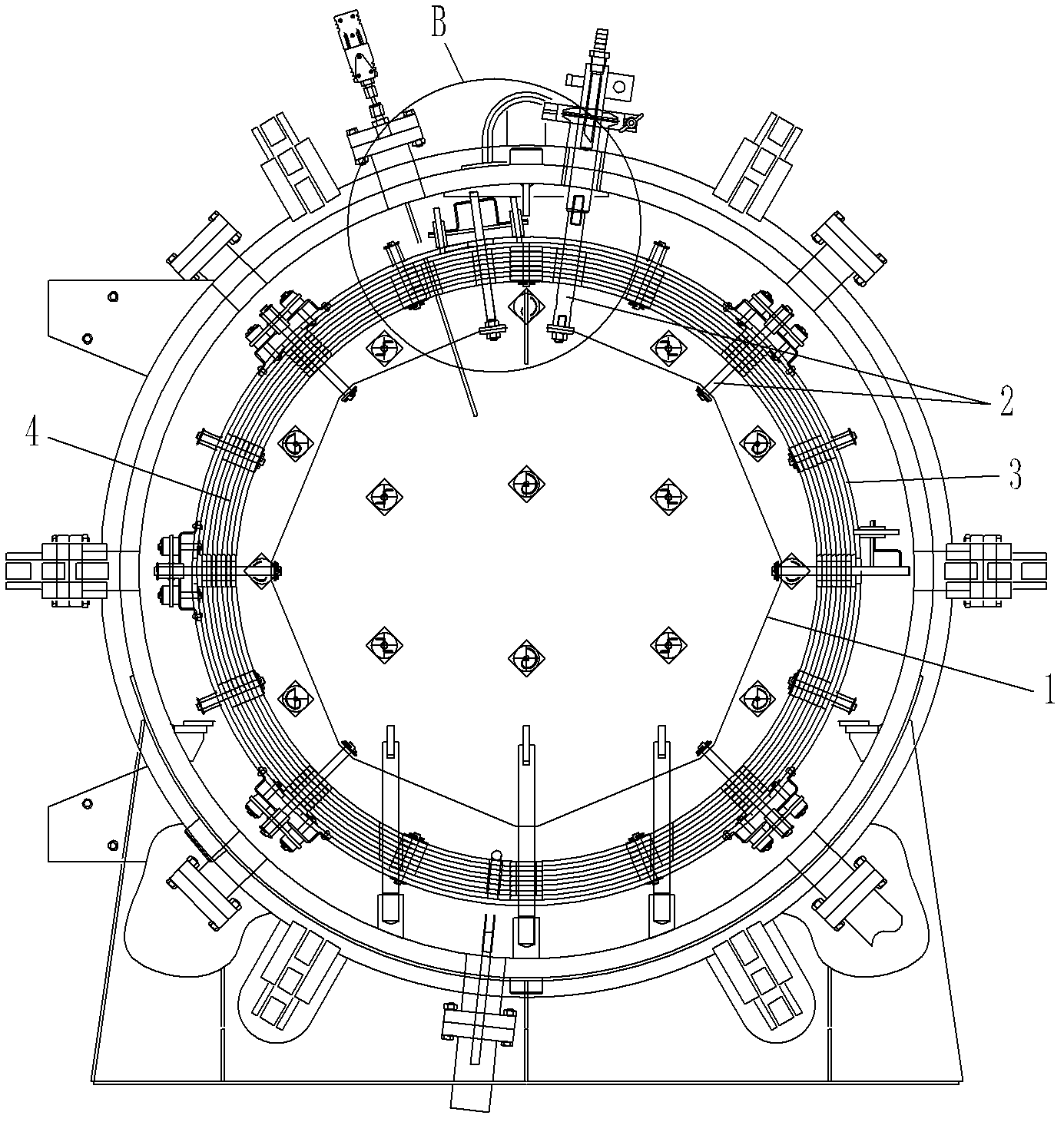
[0017] as attached image 3 to attach Figure 5 As shown, the present invention provides an insulation structure for leading out electrodes / leading support rods of a high-temperature furnace heater 1. A plurality of leading electrodes or leading supporting rods 2 are arranged on the heater 1 in the high-temperature furnace. These leading electrodes or leading supporting rods The rod 2 is fixed on the furnace body 3 through the through hole on the insulation screen 4 between the furnace body 3 and the heater 1 and the through hole on the furnace body 3. These lead-out electrodes or lead-out support rods 2 include electrodes with large diameters. Lead-out electrodes or lead-out support rods and small-diameter positioning lead-out electrodes or lead-out support rods, each lead-out electrode or lead-out support rod 2 and the furnace body 3 are p...


PUM


Abstract

The invention discloses an insulation structure of an leading-out electrode / leading-out support rod of a heater of a high-temperature furnace, comprising two bolts, two first insulation sleeves, four second insulation sleeves, a base plate and a support member; the two bolts are penetrated out from the wall of a furnace body; the two first insulation sleeves are respectively sheathed on the two bolts; the two first insulation sleeves are respectively sheathed by one second insulation sleeve; the support member takes the shape of an arch with two concave edges and convex middle; the base plateand the support member are respectively sheathed on the two bolts and the leading-out electrode or leading-out support rod through respective through holes; the two bolts are respectively sheathed byone second insulation sleeve and then fastened by nuts after gaskets are added; and an exposure end of the leading-out electrode or leading-out support rod is positioned among the heater, a heat insulation screen, the furnace body, the base plate and the support member through a locking pin. The insulation structure is arranged outside the furnace body and far away from the heater with the highest temperature, so that the limit of the highest reachable temperature is released; and the insulation structure is simple in structure, easy for implementation, good in insulation effect and suitable for popularization and use in high-temperature furnaces.

Description

technical field [0001] The invention relates to an insulation structure of a high-temperature furnace heater lead-out electrode / lead-out support rod. Background technique [0002] In high-temperature furnaces, the heater and the furnace body are usually positioned and fixed by means of lead-out electrodes or lead-out support rods passing through the insulation screen, and insulation is required between the furnace body and the heater. In traditional technologies (such as attached figure 1 and attached figure 2 shown), the insulation structure is set between the insulation screen and the heater, the insulation mechanism is an Al with a stepped hole in the center 2 o 3 Ceramic cylindrical parts, lead out electrodes or lead out support rods through Al 2 o 3 The ceramic cylinder and the insulation screen are fixed on the furnace body; a pin with a head protrudes from the inside of the heater and is connected to the insulating cylinder, and the pin is connected t...

Claims


Application Information

Patent Timeline
Patent Type & Authority Applications(China)
IPC IPC(8): F27D21/00H05B3/02
Inventor 李坚李红侠侯秉强
Owner 苏州先端稀有金属有限公司
Why Eureka
Try Eureka