
Flow battery test platform

A test platform and flow battery technology, applied in fuel cells, fuel cell additives, circuits, etc., can solve problems such as the inability to test the relationship between vanadium battery stack structural parameters and vanadium battery performance, and achieve high speed, high precision, wide The effect of the working area

Active Publication Date: 2015-09-16
DONGFANG ELECTRIC (CHENGDU) HYDROGEN FUEL CELL TECH CO LTD
View PDF4 Cites 2 Cited by
  • Summary
  • Abstract
  • Description
  • Claims
  • Application Information

AI Technical Summary

Problems solved by technology

[0004] The purpose of the present invention is to provide a liquid flow battery test platform to solve the technical problem that it is impossible to test the relationship between the structural parameters of the vanadium battery stack and the relevant parameters of the electrolyte and the performance of the vanadium battery

Method used


Image

  • Flow battery test platform
  • Flow battery test platform
  • Flow battery test platform

Examples


Embodiment Construction

[0028] The embodiments of the present invention will be described in detail below with reference to the accompanying drawings, but the present invention can be implemented in many different ways defined and covered by the claims.

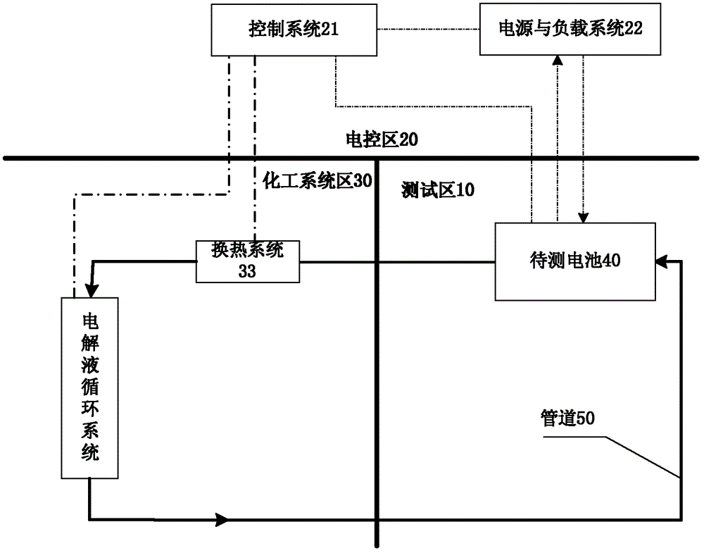
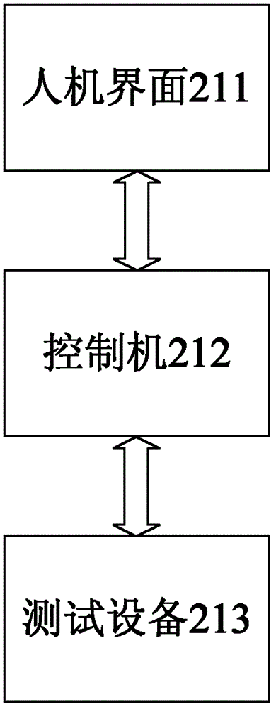
[0029] see Figure 2 to Figure 7 , according to the flow battery test platform of the present invention, comprising: a test area 10, the battery to be tested 40 is arranged in the test area 10; the electric control area 20, including a control system 21, a power supply and load system 22 and a manual debugging panel 23, and the control system 21 is electrically or wirelessly connected to the power supply and the load system 22, and the control system 21 is electrically or wirelessly connected to the manual debugging panel 23, and the power supply and the load system 22 are electrically or wirelessly connected to the test area 10; the chemical system area 30 includes the electrolyte circulation system , the chemical system area 30 is electrically or ...


PUM


Abstract

A flow battery testing platform comprises a testing area (10), a battery (40) to be tested being disposed in the testing area (10); an electric control area (20), comprising a control system (21), a power and load system (22) and a manual debugging panel (23), the control system (21) being electrically or wirelessly connected with the power and load system (22), the control system (21) being electrically or wirelessly connected with the manual debugging panel (23), and the power and load system (22) being electrically or wirelessly connected with the testing area (10); and a chemical system area (30), comprising an electrolyte cycling system, the chemical system area (30) being electrically or wirelessly connected with the electric control area (20), and the electrolyte cycling system being communicated with the testing area (10) through a pipeline (50). A hardware system of the flow battery testing platform is designed in a sectional way according to functions, which is convenient for modular machining and mounting, so that the integral structure is compact and neat, the operation is convenient and the relationships between a structure parameter and an electrolyte-related parameter of a vanadium battery stack and performance of the vanadium battery can be detected more accurately.

Description

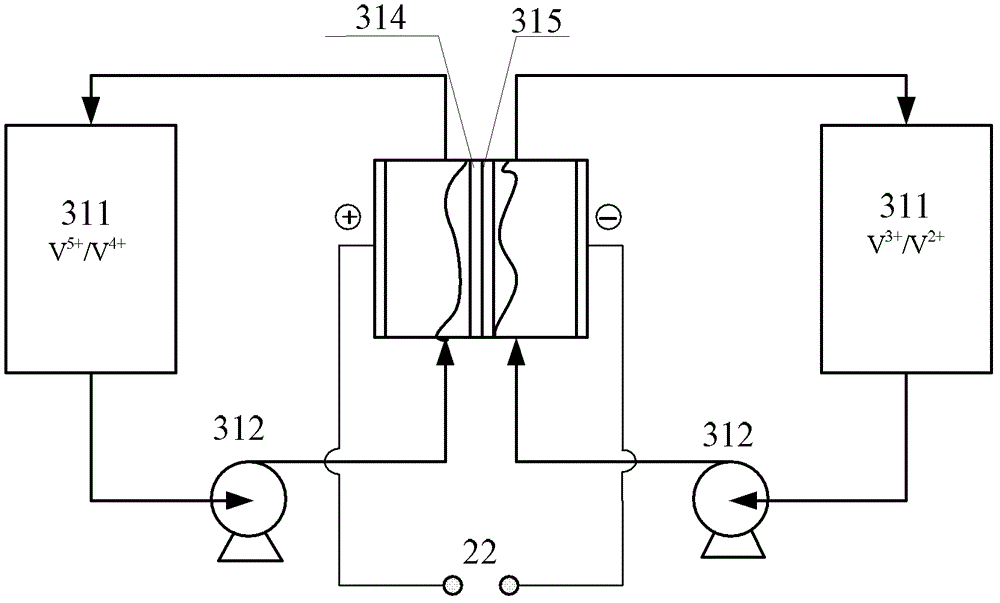
technical field [0001] The invention relates to the field of liquid flow battery testing, in particular, to a liquid flow battery testing platform. Background technique [0002] Vanadium redox battery (Vanadium Redox Battery, hereinafter referred to as vanadium battery) is a battery device based on the redox reaction principle of metal vanadium in different valence states, that is, charging and discharging through electrochemical reactions. figure 1 Shown is a schematic diagram of the working principle of the vanadium battery. The vanadium battery system is mainly composed of a battery stack, an electrolyte liquid storage tank 311, a circulation pump 312 and pipelines. The vanadium batteries are respectively V 3+ / V 2+ , V 5+ / V 4+ As the redox pair at the two poles of the battery, the vanadium ion solution in the corresponding valence state is used as the electrolyte at the two poles respectively. Electrolyte flow channel 315 . During charging and discharging, the elec...

Claims


Application Information

Patent Timeline
Patent Type & Authority Patents(China)
IPC IPC(8): G01R31/36
CPCH01M8/04477H01M8/04283G01R31/3631H01M8/188Y02E60/528G01R31/386Y02E60/50
Inventor 汤浩李云殷聪陶诗涌高建龙李婷
Owner DONGFANG ELECTRIC (CHENGDU) HYDROGEN FUEL CELL TECH CO LTD
Learn More