
Positioning system for head-up display

A head-up display and positioning system technology, applied in the field of positioning systems, can solve the problems of reducing the size of the head-up display system, unable to freely change or replace, unable to provide design freedom, etc.

Active Publication Date: 2012-07-25
MAGNA ELECTRONICS SOLUTIONS
View PDF3 Cites 21 Cited by
  • Summary
  • Abstract
  • Description
  • Claims
  • Application Information

AI Technical Summary

Problems solved by technology

However, this type of positioning device requires considerable space due to the number of parts required for precise movement, thus limiting the possibility of reducing the size of the head-up display system
In addition, the design does not provide the desired degree of design freedom to follow the requirements for dashboards and various windshields in the automotive market
In addition, the mechanism design of its two main functions, that is, the mechanism design of beam splitter movement and beam splitter angle adjustment is very related to each other, so the mechanism design of beam splitter movement and beam splitter angle adjustment cannot be freely changed or replaced

Method used


Image

  • Positioning system for head-up display
  • Positioning system for head-up display
  • Positioning system for head-up display

Examples


Embodiment Construction

[0022] In accordance with the above purpose, the technical means and effects thereof adopted in the present invention are described with reference to preferred embodiments and accompanying drawings.

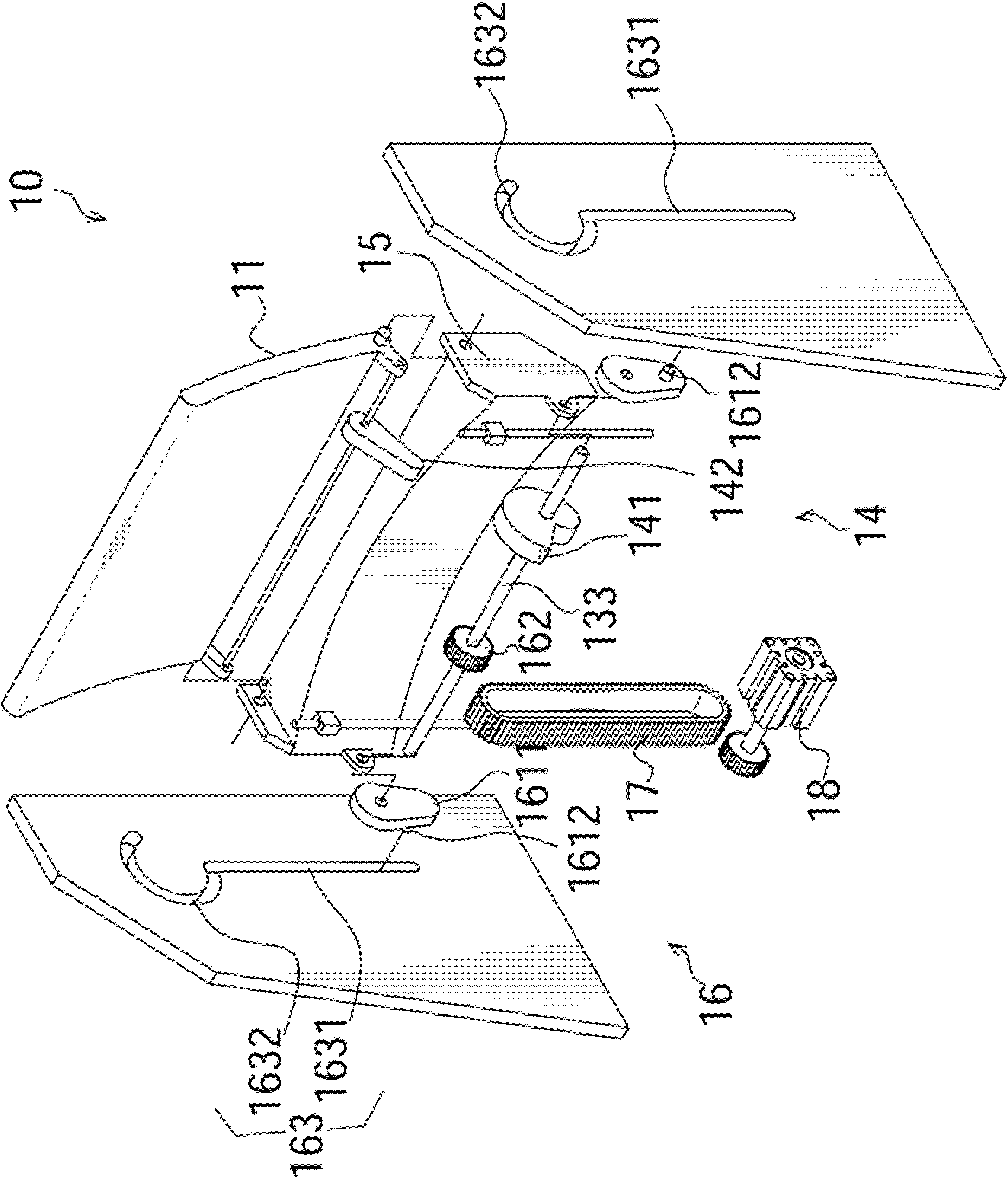
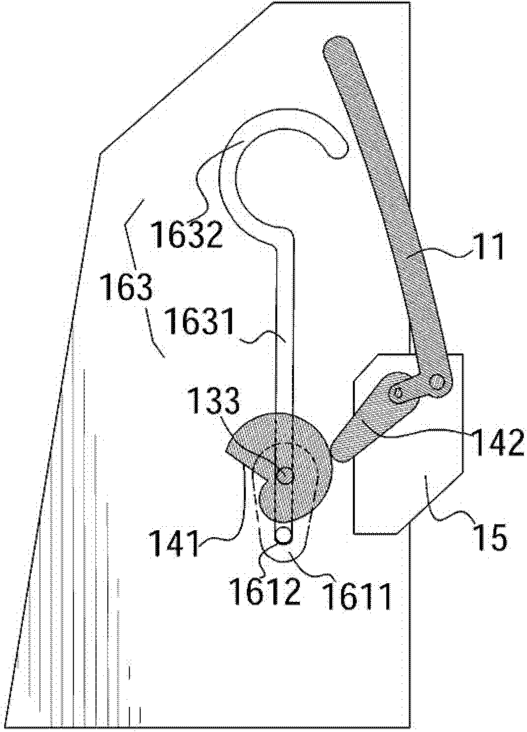
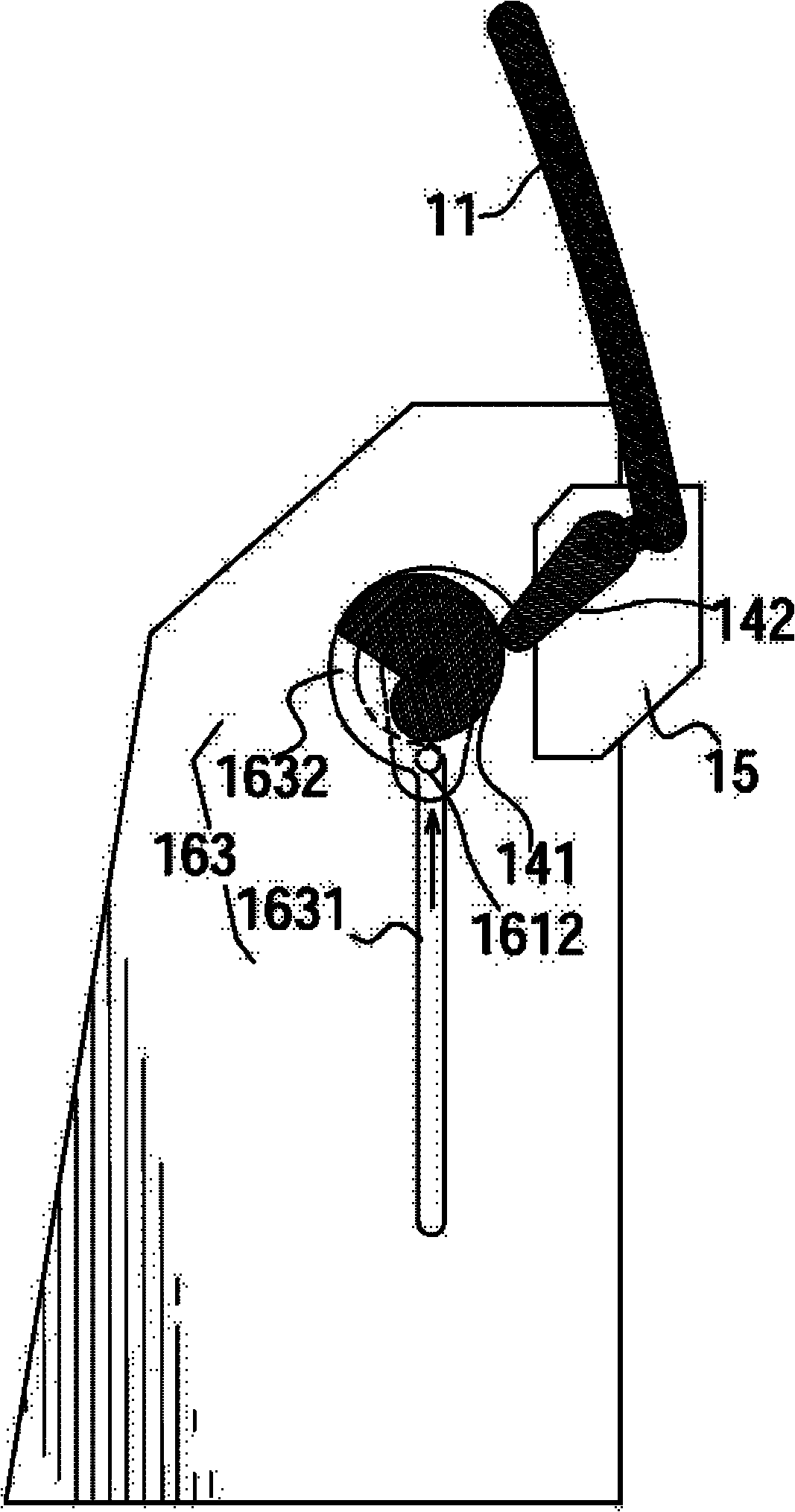
[0023] Such as figure 1 As shown, the positioning system 10 of the head-up display of the present invention includes a beam splitter carrier 15; a beam splitter (combiner) 11 rotatably arranged on the beam splitter carrier 15; A moving mechanism 13 for moving between operating positions; an angle adjusting mechanism 14 for adjusting the inclination angle of the beam splitter 11 ; and a driving mechanism 16 for alternately driving the moving mechanism 13 and the angle adjusting mechanism 14 .

[0024] In this embodiment, the moving mechanism 13 includes a rotating shaft 133 rotatably disposed on the beam splitter carrier 15 . The driving mechanism 16 includes a driving gear 162 , a guiding groove 163 and a guiding member 1611 . The driving gear 162 and the guiding member 1611 ar...


PUM


Abstract

The invention relates to a positioning system for a head-up display which comprises a combiner carrier being moved between a first position and a second position; a combiner rotatbly disposed on the combiner carrier and a tilt angle of the combiner being adjusted; and a driving mechanism for alternatively driving the movement of the combiner and the tilt angle adjustment of the combiner.

Description

technical field [0001] The invention relates to a positioning system for a head-up display, in particular to a positioning system for moving a combiner in the head-up display and adjusting its angle. Background technique [0002] Head-Up Display (HUD) was first developed in military aircraft, but it has been gradually used in commercial aircraft, automobiles and other applications. Usually, the head-up display system mainly includes a beam splitter (Combiner), a projector and a data processor (such as a computer). The beam splitter is arranged in front of the driver / pilot to display information or visual images projected from the projector. In practical applications, the beam splitter is designed to be movable between a parking position (when not in use) and an operating position (when in use). The movement of the beamsplitter between the storage position and the operating position can be realized by using the positioning system of the head-up display. In addition, the po...

Claims


Application Information

Patent Timeline
Patent Type & Authority Applications(China)
IPC IPC(8): G02B27/01G02B7/00
CPCG02B7/005G02B2027/0156G02B27/0149
Inventor H.伦普夫C.候夫A.诺耶勒
Owner MAGNA ELECTRONICS SOLUTIONS
Learn More