Lifter automatic welding system

An automatic welding and lifting technology, which is applied in the direction of welding equipment, auxiliary welding equipment, welding/cutting auxiliary equipment, etc., can solve the problems such as welding of parts that cannot be lifted, to improve clamping efficiency, easy to operate, and save auxiliary working time Effect

Inactive Publication Date: 2019-05-31
SICHUAN VOCATIONAL & TECHN COLLEGE
View PDF7 Cites 1 Cited by
  • Summary
  • Abstract
  • Description
  • Claims
  • Application Information

AI Technical Summary

Problems solved by technology

[0005] The present invention overcomes the deficiencies of the prior art, provides an automatic welding system that can weld any position of elevator parts, and solves the problem that the existing welding device cannot weld the parts of the elevator in all directions

Method used


Image

  • Lifter automatic welding system
  • Lifter automatic welding system
  • Lifter automatic welding system

Examples


Embodiment 1

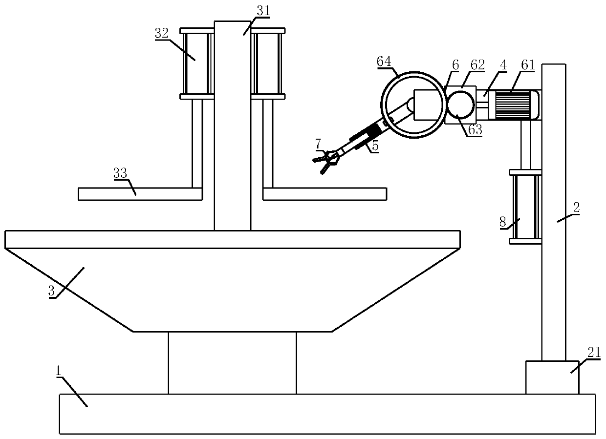
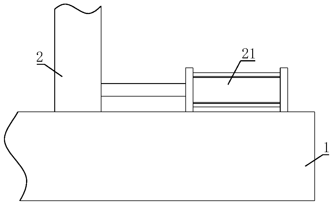
[0027] Such as figure 1 , figure 2 As shown, an automatic welding system for an elevator is characterized in that it includes a base 1, a slide groove is provided on the base 1, a bracket 2 is sleeved in the slide groove, and a traverse cylinder 21 for driving the movement of the bracket 2 is installed on the base 1. , The piston rod of the traverse cylinder 21 is fixed to the bracket 2. The base 1 is also installed with a welding table 3, the bracket 2 is installed with a lifting frame 4, the other end of the lifting frame 4 is hinged with a tilting mechanism 5, and the lifting frame 4 is installed There is a driving mechanism 6 for driving the tilting mechanism 5 to tilt, the other end of the driving mechanism 6 is connected with the tilting mechanism 5; the other end of the tilting mechanism 5 is connected with a clamping mechanism 7 for clamping the welding rod; on the welding table 3 A fixing frame 31 is installed, a pressing cylinder 32 is installed on the fixing frame 31...

Embodiment 2

[0030] On the basis of the first embodiment, the driving mechanism 6 includes a bidirectional motor 61, the output shaft of the bidirectional motor 61 is connected with a reducer 62, the bidirectional motor 61 and the reducer 62 are both installed on the lifting frame 4, the output of the reducer 62 A driving gear 63 is connected to the shaft, a driven gear 64 is fixed on the tilting mechanism 5, and the driving gear 63 meshes with the driven gear 64.

[0031] The driving mechanism 6 includes a bidirectional motor 61. After the bidirectional motor 61 is started, the reducer 62 drives the driving gear 63 to rotate, and the driving gear 63 drives the driven gear 64 on the tilting mechanism 5 to rotate, and the tilting mechanism 5 tilts accordingly, and the electrode The angle of inclination is adjusted to facilitate the welding rod to extend into the hidden position of the workpiece.

Embodiment 3

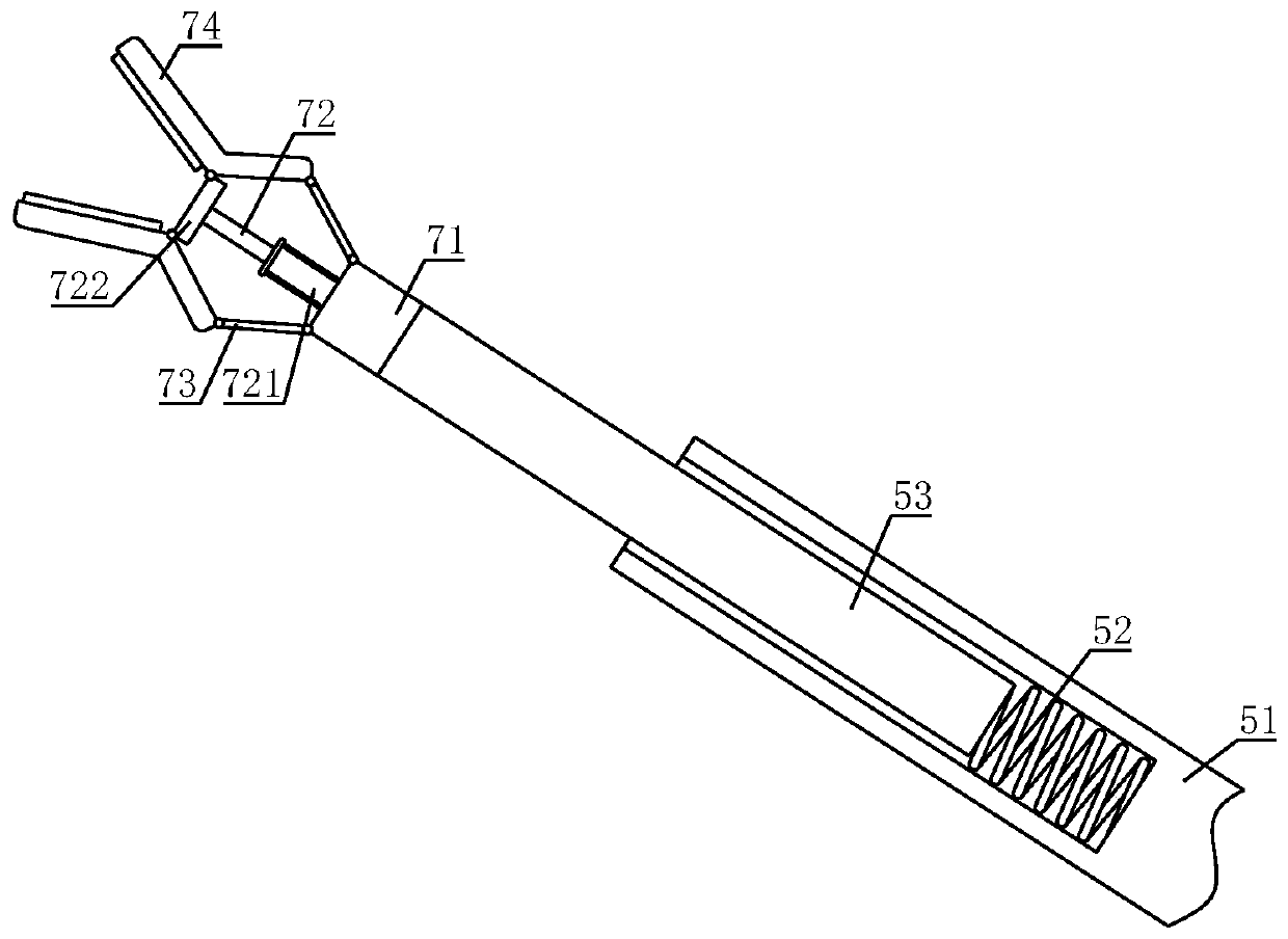
[0033] Such as image 3 As shown, on the basis of Embodiment 1 or Embodiment 2, the clamping mechanism 7 includes a fixing block 71, one end of the fixing block 71 is connected with the tilting mechanism 5, and the other end of the fixing block 71 is respectively connected with a stretching assembly 72 and two rockers 73, the stretching assembly 72 is fixed with the fixed block 71, the rocker 73 is hinged with the fixed block 71, the other end of the rocker 73 is hinged with a clamping claw 74, the middle of the two clamping claws 74 are respectively connected with One end of the stretching assembly 72 away from the fixed block 71 is hinged.

[0034] The rocker 73, the clamping claw 74, and the stretching assembly 72 form a rocker slider mechanism. When the stretching assembly 72 is retracted, the two clamping claws 74 rotate toward each other under the pulling of the stretching assembly 72, so that the two clamping claws 74 can clamp the welding rod, which realizes the rapid cl...


PUM


Abstract

The invention relates to the field of lifter welding, in particular to a lifter automatic welding system. The system comprises a base, a sliding groove is formed in the base, a support is sleeved withthe sliding groove, a transverse moving air cylinder used for driving the support to move is arranged on the base, a piston rod of the transverse moving air cylinder is fixed to the support, a welding table is mounted on the base, a lifting frame is arranged on the support, the other end of the lifting support is hinged with a tilting mechanism, a driving mechanism used for driving the tilting mechanism to achieve tilting is arranged on the lifting frame, the other end of the driving mechanism is connected with the tilting mechanism, the other end of the tilting mechanism is connected with aclamping mechanism used for clamping a welding strip, a fixed frame is arranged on the welding table, a pressing air cylinder is arranged on the fixed frame, and a pressing plate used for pressing a part to be welded is fixed to a piston rod of the pressing air cylinder. According to the automatic welding system, the any position of a lifter part can be welded.

Description

Technical field [0001] The invention relates to the field of elevator welding, in particular to an elevator automatic welding system. Background technique [0002] The elevator is a mechanical equipment that uses a cage or platform to transport people and objects up and down along the guide rail. It is an indispensable machine for completing transportation and lifting tasks. It is a basic and very important electromechanical equipment in all walks of life in the national economy. . At present, there are big differences in elevator production technology at home and abroad, especially the welding technology among them. Almost all top elevator manufacturers are concentrated in a few countries and regions such as North America, Japan and Europe. After decades of technological reform and innovation, the elevator production in these countries and regions has the advantages of high production efficiency, high assembly level and advanced technology. The entire production is basically f...

Claims


Application Information

Patent Timeline
Patent Type & Authority Applications(China)
IPC IPC(8): B23K37/047B23K37/04B23K37/00
Inventor 游代乔罗辉
Owner SICHUAN VOCATIONAL & TECHN COLLEGE
Why Eureka
Try Eureka