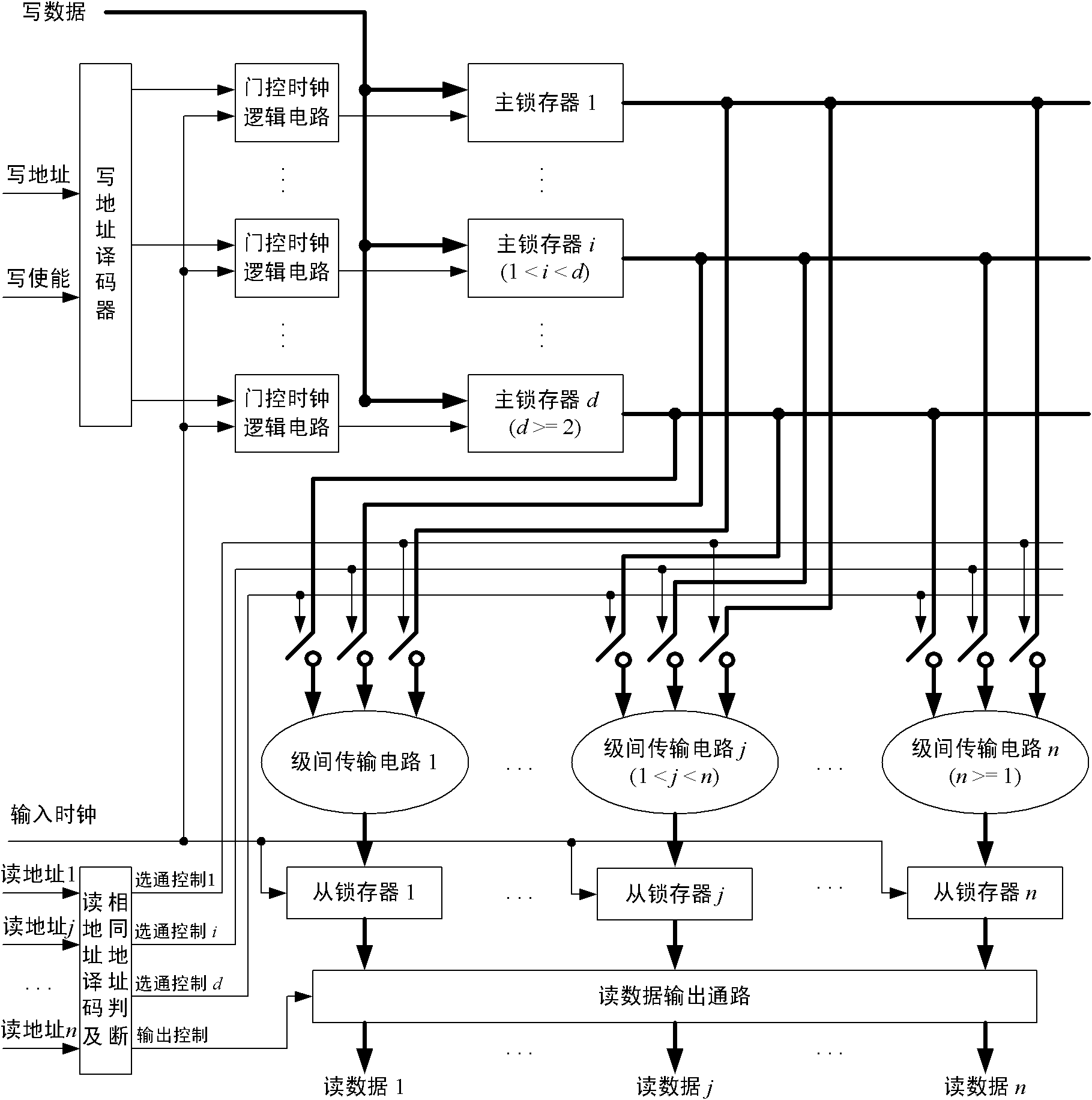
Write-once read-many disc internal memory
An on-chip memory and latch technology, applied in the field of multi-read single-write on-chip memory, can solve the problems of area consumption and slow speed, and achieve the effect of saving clock cycles
- Summary
- Abstract
- Description
- Claims
- Application Information
AI Technical Summary
Problems solved by technology
Method used
Image
Examples
Embodiment 1
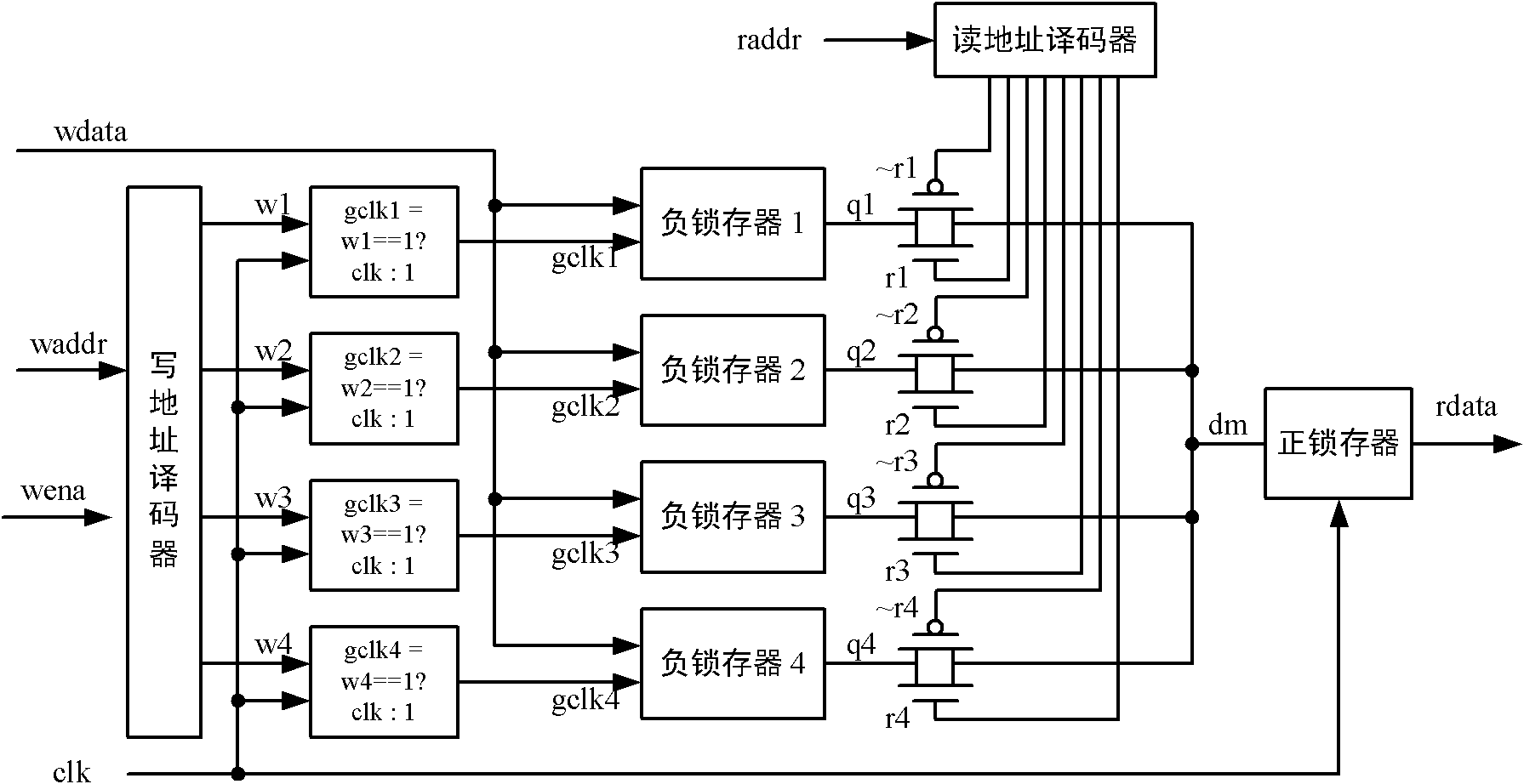
[0048] One embodiment is a 1R1W dual-port memory with a data port bit width of 1-bit and a storage capacity of 4 bits, as shown in the attached figure 2 shown.
[0049] The input and output ports of the memory are as follows:
[0050] port name
port direction
port width
port description
clk
input
1
Memory input clock signal
wena
input
1
memory write enable signal
waddr
input
2
memory write address
wdata
input
1
memory write data
raddr
input
2
memory read address
rdata
output
1
memory read data
[0051] The first level of the memory includes a write address decoder, 4 gating clock circuits, and 4 negative latches. The input of the write address decoder is clk, wena and waddr, and generates 4 decoded address control output signals w1, w2, w3, w4 synchronized with the rising edge of clk. Its logical relationship is shown in t...
Embodiment 2
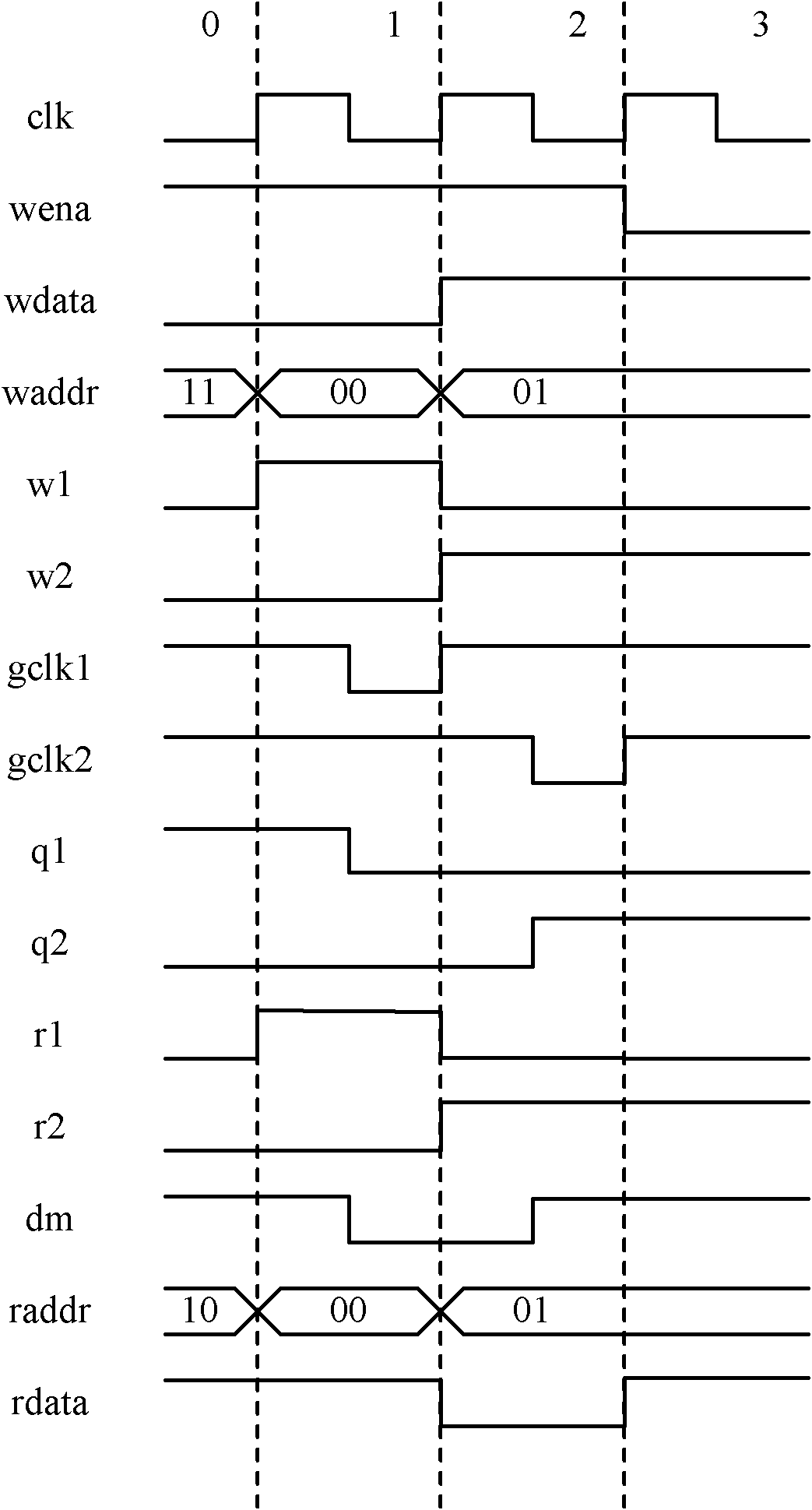
[0070] The only difference between Embodiment 2 and Embodiment 1 is: the output r1, r2, r3, r4 of the read address decoder and their opposite signals ~r1, ~r2, ~r3, ~r4 are synchronized with the falling edge of clk. Therefore, only the timing of reading data is changed. attached Figure 4 The timing diagram is given, taking r1 and r2 as examples, the process of reading data is:
[0071] Clock cycle 0: raddr selects negative latch 3, and rdata is the value 1 stored in negative latch 3.
[0072] Clock cycle 1: raddr changes on the falling edge of the clock cycle, selecting negative latch 1. Then r1=1, dm=q1. However, the positive latch is already in the latched state, and the value of rdata is still the value 1 corresponding to the previous negative latch 3.
[0073] Clock cycle 2: After the rising edge arrives, the positive latch starts to sample dm, at this time rdata=q1. raddr changes on the falling edge of the clock cycle, selecting negative latch 2. Then r2=1, dm=q2. ...
Embodiment 3
[0076] This embodiment is a 2R1W multi-port memory with a data port bit width of 1-bit and a storage capacity of 4 bits, see appendix Figure 5 .
[0077] Compared with Embodiment 1, the first stage of this embodiment is exactly the same as that of Embodiment 1. The difference is:
[0078] There are two sets of interstage transfer circuits and positive latches. Each group of inter-stage transmission circuits, positive latches, and their connection relationship with the first stage are the same, and are equivalent to Embodiment 1.
[0079] The read address decoding and identical address judgment module needs to decode two read address inputs raddr1 and raddr2 to generate strobe signals r1_1, r1_2, r1_3, r1_4, r2_1, r2_2, r2_3, r2_4 and their opposite signals. When raddr1 and raddr2 are different, the logical relationship between raddr1 and r1_1, r1_2, r1_3, r1_4 is the same as the logical relationship between raddr2 and r2_1, r2_2, r2_3, r2_4, and is equivalent to raddr and ...
PUM
 Abstract
Description
Claims
Application Information
 - R&D
- Intellectual Property
- Life Sciences
- Materials
- Tech Scout
- Unparalleled Data Quality
- Higher Quality Content
- 60% Fewer Hallucinations
Browse by: Latest US Patents, China's latest patents, Technical Efficacy Thesaurus, Application Domain, Technology Topic, Popular Technical Reports.
© 2025 PatSnap. All rights reserved.Legal|Privacy policy|Modern Slavery Act Transparency Statement|Sitemap|About US| Contact US: help@patsnap.com


