Pay-off apparatus for superfine wires

A wire-releasing device and wire technology, applied in the direction of cable/conductor manufacturing, electrical components, circuits, etc., can solve problems such as wire breakage, stranded wire quality and pass rate drop, breakage, etc., so that the wire-releasing process is smooth and not easy to break The effect of maintaining stable thread and pay-off tension

Active Publication Date: 2012-07-25
苏州久隆新材料科技有限公司
View PDF5 Cites 9 Cited by
  • Summary
  • Abstract
  • Description
  • Claims
  • Application Information

AI Technical Summary

Problems solved by technology

Existing pay-off racks are generally controlled by a motor to pull the wire to pay out. This kind of ultra-fine wire with a diameter of less than 0.03 mm will inevitably break when paying out, especially when the motor starts and stops instantly, and when the motor pulls the wire. When the pulling speed becomes faster or slower, due to the rapid change of the tension of the pay-off, it is very easy to cause breakage during pay-off, which will reduce the quality and pass rate of the stranded wire, and even affect the progress of production.

Method used


Image

  • Pay-off apparatus for superfine wires
  • Pay-off apparatus for superfine wires
  • Pay-off apparatus for superfine wires

Examples


Embodiment 1

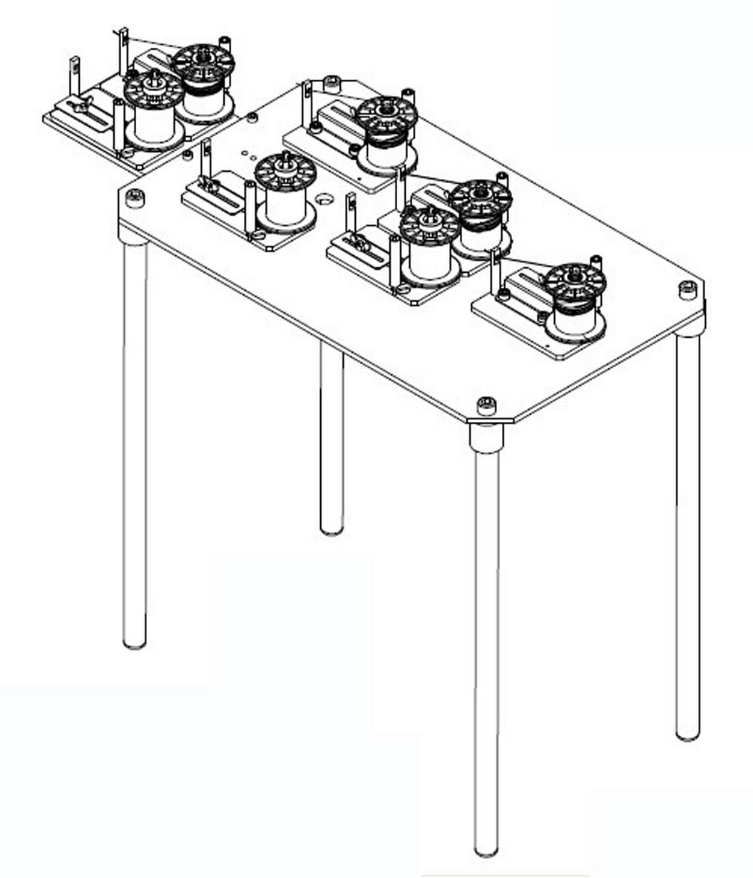
[0026] like figure 1 As shown, the pay-off device of this embodiment is used for the pay-off of ultra-fine wires, and includes seven pay-off racks; five pay-off racks are horizontally arranged on the workbench, arranged in three rows in a golden shape, and the remaining The two pay-off racks are horizontally arranged on the outer protruding surface protruding from the workbench. The number and arrangement of these pay-off racks can be arranged arbitrarily according to the needs of actual twisting, so that the twisting process is convenient and it is better not to be entangled and knotted between the lines.

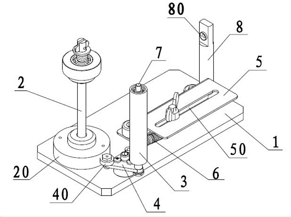
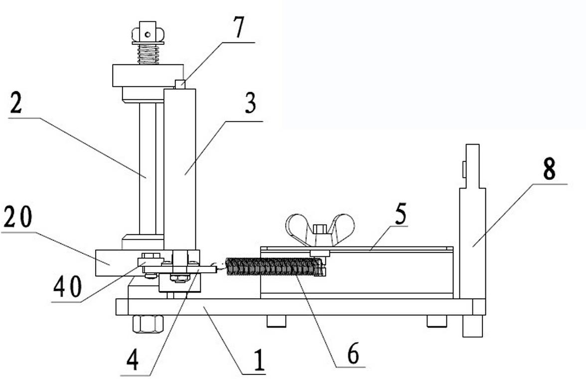
[0027] like Figure 2~5 As shown, the pay-off frame includes a base 1, which is vertically arranged at one end of the base 1, and is used to cover a pay-off main shaft 2 with a reel 9 wound with a very fine wire, and a fixed shaft 7, which is set on the fixed shaft 7, the traction guide roller 3 that is used to pull the ultra-fine wire when unwinding, the pole 8 tha...

Embodiment 2

[0032] by Figure 6 The installation of the wire reel shown and the way of paying off the wire are described as follows to the working process of the pay-off stand of embodiment 1:

[0033] Set the wire reel 9 of the ultra-fine wire on the pay-off spindle 2, and hold it by the rotating tray 20. The extension spring 6 is locked at a certain position on the guide rail 50 of the fixed plate 5 and maintains a certain tension, so that the adjustment disc 4 The friction wheel 40 is against the edge of the rotating tray 20 and gives a pressure to the rotating tray 20. Since the position of the extension spring 6 on the guide rail 50 is adjustable, the pressure of the friction wheel 40 on the rotating tray 20 is also adjustable. This pressure needs to be adjusted in advance. After testing or calculation, it is obtained to keep the tension of the ultra-fine wire at the best value when paying off, so as to balance the paying off.

[0034] When unwinding, the ultra-fine wire is pu...


PUM


Abstract

The invention relates to a pay-off apparatus for superfine wires, which comprises a plurality of pay-off stands, wherein each pay-off stand comprises a base, a pay-off spindle, a traction guide roller and a tension spring adjusting mechanism, wherein the lower part of the pay-off spindle is provided with a rotating tray which can rotate around the axial direction of the pay-off spindle; the tension spring adjusting mechanism comprises an adjusting disc, a fixed plate and a tension spring connected between the adjusting disc and the fixed plate; and the adjusting disc is also provided with a friction wheel which is in friction contact with the rotating tray, and the traction guide roller is arranged on the adjusting disc. In general, the rotating tray overcomes the friction force and pressure of the friction wheel and then carries out wire pay-off normally; when the pay-off speed increases, the tensile force of a superfine wire on the traction guide roller increases firstly so as to drive the adjusting disc to have a trend that the tensile force of the tension spring is overcome and the adjusting disc is away from the rotating tray, so that the friction force and pressure between the friction wheel and the rotating tray are reduced, and the pay-off speed of the superfine wire increases; and finally, the pay-off tensile force falls back and keeps stable. By using the pay-off apparatus disclosed by the invention, the tensile force in a pay-off process is balanced, and a situation of wire breakage is not easily caused.

Description

technical field [0001] The invention relates to a cable production equipment, in particular to a pay-off device for ultra-fine wires . Background technique [0002] With the rapid development of household appliances and electronic communication industries, electronic products such as computers and mobile phones have been widely used. Silver plating, tin plating or pure copper are often used in such electronic products and other chips such as medical precision instruments. Ultra-fine wires made of materials, their wire diameter is generally less than 0.03 mm. This kind of ultra-fine wire needs to use a pay-off device during the processing process such as stranding, which generally includes a plurality of pay-off frames. Twisted into strands. Existing pay-off racks are generally controlled by a motor to pull the wire to pay out. This kind of ultra-fine wire with a diameter of less than 0.03 mm will inevitably break when paying out, especially when the motor starts and sto...

Claims


Application Information

Patent Timeline
Patent Type & Authority Applications(China)
IPC IPC(8): H01B13/00H01B13/02
Inventor 阎加军徐向东
Owner 苏州久隆新材料科技有限公司
Why Eureka
Try Eureka