
Antenna-feeder system and phase calibration method

An antenna-feeder system and phase difference technology, applied in the field of communications, can solve the problems of reducing the effect of polarization diversity, inconsistency of the incoming signal phase, and inability to calibrate the phase error, etc., and achieve the effect of improving the effect of polarization diversity.

Active Publication Date: 2014-12-24
CHINA UNITED NETWORK COMM GRP CO LTD
View PDF6 Cites 0 Cited by
  • Summary
  • Abstract
  • Description
  • Claims
  • Application Information

AI Technical Summary

Problems solved by technology

Since the radio frequency signals of the two polarized arrays of the dual-polarized antenna are transmitted through independent feed networks (power dividing network and phase-shifting network), the cable length error in the feeding network, the influence of the power dividing network and the shifting of the phase-shifting network Factors such as phase error cause the phases of the feed signals of the two polarized arrays to be inconsistent. In the above scheme, although the phase change of the signal phase is set at the phase shift control port to adjust the phase of the two polarized arrays, the two RF signals cannot be calibrated. The phase error generated by the independent feed network leads to inconsistent pitch angles of the antenna radiation pattern in the two polarization directions, and the problem of inconsistent electromagnetic wave coverage in the two polarization directions at the edge of the cell, which reduces the polarization diversity Effect

Method used


Image

  • Antenna-feeder system and phase calibration method
  • Antenna-feeder system and phase calibration method
  • Antenna-feeder system and phase calibration method

Examples


Embodiment 1

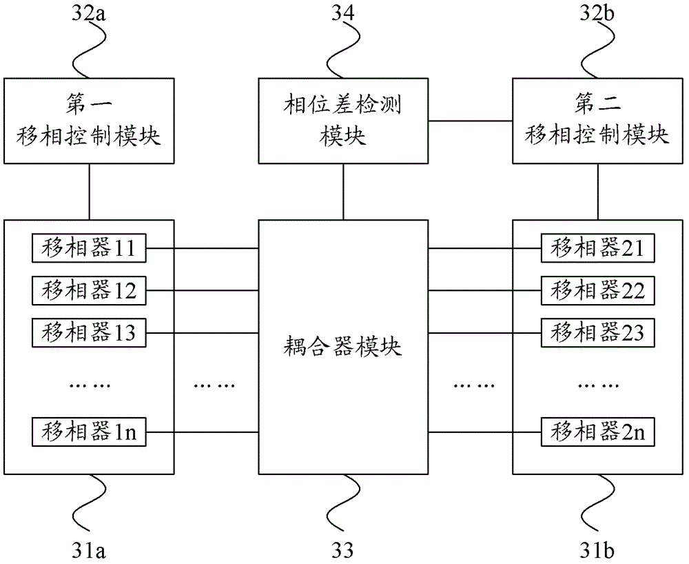
[0025] image 3 It is a schematic structural diagram of an antenna feeder system according to Embodiment 1 of the present invention. Such as image 3 As shown, the antenna feeder system includes a first phase shifting network 31a, a second phase shifting network 31b, a first phase shifting control module 32a, a second phase shifting control module 32b, a coupler module 33 and a phase difference detection module 34, wherein :

[0026] The first phase shifting network 31a and the second phase shifting network 31b include the same number of phase shifters, and the phase shifters in the first phase shifting network 31a are in phase with the phase shifters in the second phase shifting network 31b correspond;

[0027] The first phase shift control module 32a is configured to receive a phase change amount, and adjust the phase shift amount of the phase shifter in the first phase shift network 31a according to the phase change amount;

[0028] A coupler module 33, configured to co...

Embodiment 2

[0038] Figure 4 It is a schematic structural diagram of an antenna feeder system according to Embodiment 2 of the present invention. In this embodiment, a coupler group including multiple single-channel couplers is used as an example for illustration, such as Figure 4 As shown, the coupler group includes 2n single-channel couplers, and one end of each coupler is respectively connected to the phase shifters 11 to 1n in the first phase shifting network 43a and the phase shifters 21 to 1n in the second phase shifting network 43b. 2n, and the other end is respectively connected to the polarized antenna corresponding to the phase shifter, for coupling out the radio frequency signal that is phase-shifted by the phase shifter and used as the input signal of the polarized antenna.

[0039] Figure 5 for Figure 4 A schematic diagram of the signal transmission process of the antenna feeder system shown. Such as Figure 5 shown, including:

[0040] Step S501, the first radio fre...

Embodiment 3

[0053] On the basis of the above embodiments, in this embodiment, the phase difference detection module and the second phase shifting control module are only connected through one line, and correspondingly, the phase difference detection module is also used to set a sign for the phase difference The second phase shifting control module is also used to determine the phase shifter in the second phase shifting network corresponding to the phase difference according to the identification, and adjust the phase shifting of the corresponding mover according to the phase difference quantity.

[0054] Specifically, still with Figure 4 The antenna feed system shown in is taken as an example, the phase difference detection module 48 receives the signal provided by the coupler through n pairs of input ports, for example, the phase shifter 11 and the phase shifter 21 coupled to the first pair of input ports receive the coupler The phase-shifted low-power signal is based on the low-power ...


PUM


Abstract

The invention provides an antenna-feeder system and a phase calibration method. The antenna-feeder system comprises a first phase shift network and a second phase shift network, wherein the first phase shift network and the second phase shift network comprise corresponding phase shift devices with the same number, the antenna-feeder system also comprises a first phase shift control module, a coupler module, a phase difference detection module and a second phase shift control module, the first phase shift control module is used for receiving phase change quantity control signals and regulates the phase shift quantity of the phase shift devices in the first phase shift network according to the phase change quantity control signals, the coupler module is used for coupling radio frequency signals of each path of phase shift devices passing through the first phase shift network and the second phase shift network, in addition, the radio frequency signals are sent to the phase difference detection module, the phase difference detection module is used for obtaining the phase difference of the phase shift devices with the corresponding relationship in the first phase shift network and the second phase shift network according to the phase value of the radio frequency signals and sending the phase difference to the second phase shift control module, and the second phase shift control module is used for regulating the phase shift quantity of the phase shift devices in the second phase shift network according to the phase difference.

Description

technical field [0001] The invention relates to signal calibration technology, in particular to an antenna feed system and a phase calibration method, and belongs to the technical field of communication. Background technique [0002] In mobile communication, the pitch angle of the antenna is an important parameter for network maintenance and optimization, and setting the pitch angle of the antenna reasonably is the basic guarantee for the quality of the entire mobile communication network. The adjustment of the elevation angle of the antenna beam can be realized by adjusting the relative phase of the feed signal on each array element. [0003] A dual-polarized antenna consists of two groups of radiating elements with mutually orthogonal polarization directions, and each group of radiating elements has the same array characteristics. Since the correlation between signals in different polarization directions is weak, a dual-polarization antenna can produce a better polarizati...

Claims


Application Information

Patent Timeline
Patent Type & Authority Patents(China)
IPC IPC(8): H01Q3/30H01Q23/00
Inventor 李新中侯竞雄杨军范斌吕召彪王健全陈新明殷黎蓉
Owner CHINA UNITED NETWORK COMM GRP CO LTD
Learn More