Base station antenna and multi-port phase shifter thereof

A phase shifter and multi-port technology, applied in antennas, waveguide devices, circuits, etc., can solve the problem of extending the longitudinal length of phase shifting circuits and cavities, increasing the difficulty of cavity molding and electroplating, and increasing the PIM value of phase shifters and other issues, to achieve the effect of increasing the difficulty of layout, realizing miniaturization, and reducing the PIM value

Pending Publication Date: 2020-08-21
COMBA TELECOM TECH (GUANGZHOU) CO LTD
View PDF0 Cites 2 Cited by
  • Summary
  • Abstract
  • Description
  • Claims
  • Application Information

AI Technical Summary

Problems solved by technology

[0002] At present, in the field of mobile communication technology, with the continuous introduction of new standards and new spectrums, antenna equipment is required to support more spectrums, and the resulting problem is that the number of phase shifters in base station antennas continues to increase. The size is increasing and the layout of the feeding network is becoming more and more complex
[0003] like figure 1 As shown, in the existing dielectric phase shifter, its working principle is to realize the phase shift by changing the dielectric constant of the transmission line between the feed point and the antenna unit, specifically, the phase shift circuit is changed by moving the dielectric plate. The area covered by the dielectric plate can adjust the dielectric constant of the phase-shifting circuit, but the phase-shifting circuit in this structure can only be laid out along the length of the cavity. As the demand for output ports increases, the phase-shifting circuit and cavity The longitudinal length of the tube is continuously extended, which increases the difficulty of molding and electroplating of the cavity, which easily leads to an increase in the PIM value of the phase shifter, making it difficult to achieve miniaturization and also affects the performance indicators of the phase shifter

Method used


Image

  • Base station antenna and multi-port phase shifter thereof
  • Base station antenna and multi-port phase shifter thereof
  • Base station antenna and multi-port phase shifter thereof

Examples


Embodiment Construction

[0031] Embodiments of the present invention are described in detail below, examples of which are shown in the drawings, wherein the same or similar reference numerals designate the same or similar elements or elements having the same or similar functions throughout. The embodiments described below by referring to the figures are exemplary only for explaining the present invention and should not be construed as limiting the present invention.

[0032] Those skilled in the art can understand that, unless otherwise stated, the word "comprising" used in the description of the present invention refers to the presence of the features, integers, steps, operations, parts / components and / or components, but does not exclude the presence or Add one or more other features, integers, steps, operations, parts / parts, components and / or groups thereof. It should be understood that when we refer to a part / component as being "connected" to another part / component, it may be directly connected to t...


PUM


Abstract

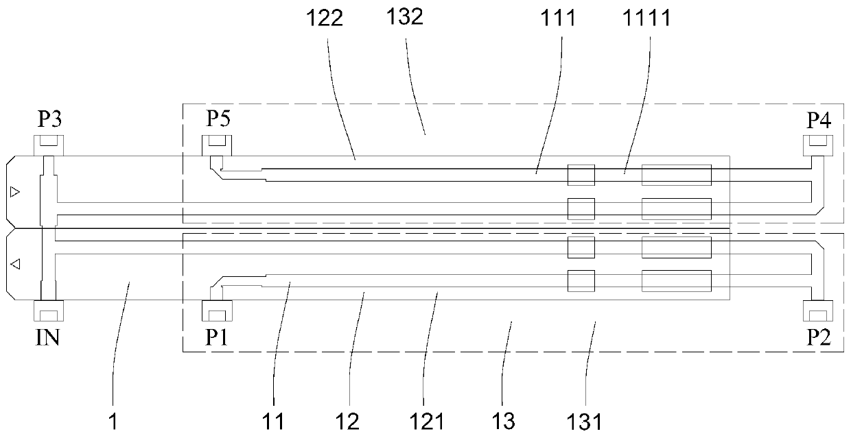
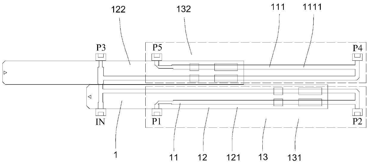
The invention provides a base station antenna and a multi-port phase shifter thereof. The multi-port phase shifter comprises a cavity, a phase shifting circuit arranged in the cavity, and dielectric plate which covers the phase shift circuit and can move along the length direction of the cavity; the phase shift circuit comprises a plurality of phase shift units and a plurality of output ports connected with the phase shift units in a one-to-one correspondence manner. At least two phase shift regions arranged along the width direction of the cavity are arranged in the cavity, and each phase shift region comprises at least one phase shift unit and one dielectric plate used for changing the dielectric constant of the phase shift unit in the phase shift region. According to the multi-port phase shifter, due to the fact that the cavity is internally provided with the at least two phase shifting areas arranged in the width direction of the cavity, the phase shifting circuit can be arranged in the width direction of the cavity, the longitudinal length of the whole structure is reduced, the transverse length of the cavity is properly increased, machining and forming of the cavity are better facilitated, the manufacturing difficulty is reduced, and good performance is guaranteed.

Description

technical field [0001] The invention relates to the technical field of mobile communication, in particular to a multi-port phase shifter and a base station antenna using the multi-port phase shifter. Background technique [0002] At present, in the field of mobile communication technology, with the continuous introduction of new standards and new spectrums, antenna equipment is required to support more spectrums, and the resulting problem is that the number of phase shifters in base station antennas continues to increase. The size continues to increase, and the layout of the feed network is becoming more and more complex. [0003] Such as figure 1 As shown, in the existing dielectric phase shifter, its working principle is to realize the phase shift by changing the dielectric constant of the transmission line between the feed point and the antenna unit, specifically, the phase shift circuit is changed by moving the dielectric plate. The area covered by the dielectric plate...

Claims


Application Information

Patent Timeline
Patent Type & Authority Applications(China)
IPC IPC(8): H01P1/18H01Q3/32
CPCH01P1/18H01Q3/32
Inventor 李明杰贾飞飞王强
Owner COMBA TELECOM TECH (GUANGZHOU) CO LTD
Why Eureka
Try Eureka