Optical fiber network system

An optical fiber network and optical fiber technology, which is applied in the field of optical fiber network systems, can solve the problems of reduced level coverage, low reliability, and multiple maintenance of equipment, and achieves stable signal, high stability and reliability, and fast network construction. Effect

Active Publication Date: 2012-07-25
深圳市虹远通信有限责任公司
View PDF2 Cites 3 Cited by
  • Summary
  • Abstract
  • Description
  • Claims
  • Application Information

AI Technical Summary

Problems solved by technology

[0002] The traditional optical fiber repeater engineering networking method is simple, but this kind of optical fiber repeater adopts a star network mode. If a remote machine is damaged, a blind area will appear in a certain area. If the near-end machine is damaged, all areas will be closed. It will become a signal blind area with a low degree of reliability. It is only applicable to the signal coverage of ordinary civil mobile communication systems with low reliability requirements, but it is not applicable in the case of high reliability requirements in rail communication systems. ; At present, there is still a way of interweaving the network with base station A and base station B respectively using optical fiber repeaters, which has a relatively high degree of reliability, but this way uses more equipment and is inconvenient to maintain, and the coverage distance can only be within 6 Within one kilometer, when the far-end machine fails, the signal will be switched twice, and in the case of the near-end machine or the main base station failure, the level coverage level of the entire line area will all drop

Method used


Image

  • Optical fiber network system
  • Optical fiber network system
  • Optical fiber network system

Examples


Embodiment 1

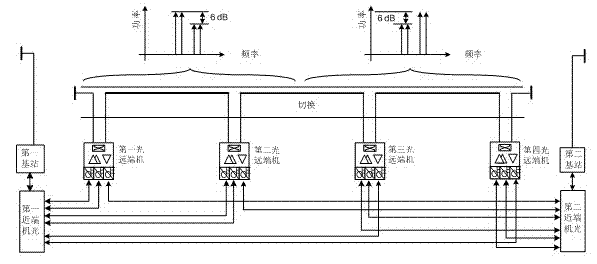
[0046] Such as figure 1 As shown, this example provides an optical fiber network system, including:

[0047] the first base station;

[0048] The first optical near-end unit is connected to the first base station;

[0049] second base station;

[0050] a second optical near-end unit connected to the second base station;

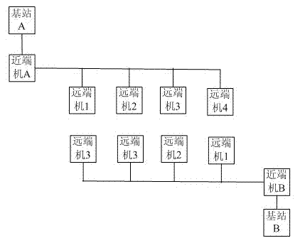
[0051] The first optical remote unit exchanges optical information with the first optical near-end unit through two optical fibers, and exchanges optical information with the second optical near-end unit through one optical fiber;

[0052] The second optical remote unit exchanges optical information with the first optical near-end unit through two optical fibers, exchanges optical information with the second optical near-end unit through one optical fiber, and exchanges optical information with the first optical remote unit connect;

[0053] The third optical remote machine exchanges optical information with the second optical near-end machine through tw...

Embodiment 2

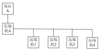
[0062] The difference from Embodiment 1 is that the first optical remote unit, the second optical remote unit, the third optical remote unit and the fourth optical remote unit in this example are connected to the first optical remote unit in a star network. One optical near-end machine and the second optical near-end machine.

[0063] This example further adopts the above-mentioned technical features, and its advantage is that it can realize a highly reliable optical fiber network system, increase the coverage area, and ensure that the working processes of the first optical near-end machine and the second optical near-end machine are mutually active and standby. interfered, on this basis, the first optical remote unit, the second optical remote unit, the third optical remote unit and the fourth optical remote unit are connected to the first optical remote unit in a star network The near-end machine and the second optical near-end machine make the networking mode more flexible,...

Embodiment 3

[0065] Different from Embodiment 1, leaky cables are used to connect the first optical remote unit, the second optical remote unit, the third optical remote unit and the fourth optical remote unit in this example.

[0066] This example further adopts the above-mentioned technical features, and its advantage is that it can realize a highly reliable optical fiber network system, increase the coverage area, and ensure that the working processes of the first optical near-end machine and the second optical near-end machine are mutually active and standby. Interference, on this basis, the first optical remote unit, the second optical remote unit, the third optical remote unit and the fourth optical remote unit are connected by leaky cables, especially in rail communication systems In the case of a long and narrow strip, the leaky cable connection is used as a coverage antenna, which is especially suitable for coverage in tunnel engineering environments, with stable signals and high r...


PUM


Abstract

The invention provides an optical fiber network system, comprising a first base station, a first optical near-end machine, a second base station, a second optical near-end machine, a first optical far-end machine, a second optical far-end machine, a third optical far-end machine and a fourth optical far-end machine, wherein the first optical far-end machine exchanges optical information with the first optical near-end machine through two optical fibers and exchanges the optical information with the second optical near-end machine through one optical fiber; the second optical far-end machine exchanges the optical information with the first optical near-end machine through two optical fibers and exchanges the optical information with the second optical near-end machine through one optical fiber; the third optical far-end machine exchanges the optical information with the second optical near-end machine through two optical fibers and exchanges the optical information with the first optical near-end machine through one optical fiber; the fourth optical far-end machine exchanges the optical information with the second optical near-end machine through two optical fibers and exchanges the optical information with the first optical near-end machine through one optical fiber; any one optical far-end machine is connected with the adjacent optical far-end machine, wherein a pre-set difference is set between strengths of input and output signals of the first optical near-end machine and the second optical near-end machine.

Description

technical field [0001] The invention relates to an optical fiber repeater, in particular to an optical fiber network system. Background technique [0002] The traditional optical fiber repeater engineering networking method is simple, but this kind of optical fiber repeater adopts a star network mode. If a remote machine is damaged, a blind area will appear in a certain area. If the near-end machine is damaged, all areas will be closed. It will become a signal blind area with a low degree of reliability. It is only applicable to the signal coverage of ordinary civil mobile communication systems with low reliability requirements, but it is not applicable in the case of high reliability requirements in rail communication systems. ; At present, there is still a way of interweaving the network with base station A and base station B respectively using optical fiber repeaters, which has a relatively high degree of reliability, but this way uses more equipment and is inconvenient t...

Claims


Application Information

Patent Timeline
Patent Type & Authority Applications(China)
IPC IPC(8): H04B10/12H04B10/25H04Q11/00
Inventor 马印斌柯玉冰林凯余华安
Owner 深圳市虹远通信有限责任公司
Why Eureka
Try Eureka