Fan module

A fan module and fan technology, applied in cooling/ventilation/heating transformation, electrical equipment construction parts, electrical components, etc., can solve problems such as cumbersome process

Inactive Publication Date: 2012-07-25
FU ZHUN PRECISION IND SHENZHEN +1
View PDF6 Cites 1 Cited by
  • Summary
  • Abstract
  • Description
  • Claims
  • Application Information

AI Technical Summary

Problems solved by technology

[0003] At present, the usual method used in the industry to securely install the fan on the heat sink is to fix the fan on the heat sink or the fan fixing frame with locking screws. However, this fixing method requires the use of relevant tools during the fan installation process To operate, the process is more cumbersome

Method used


Image

  • Fan module
  • Fan module
  • Fan module

Examples


Embodiment Construction

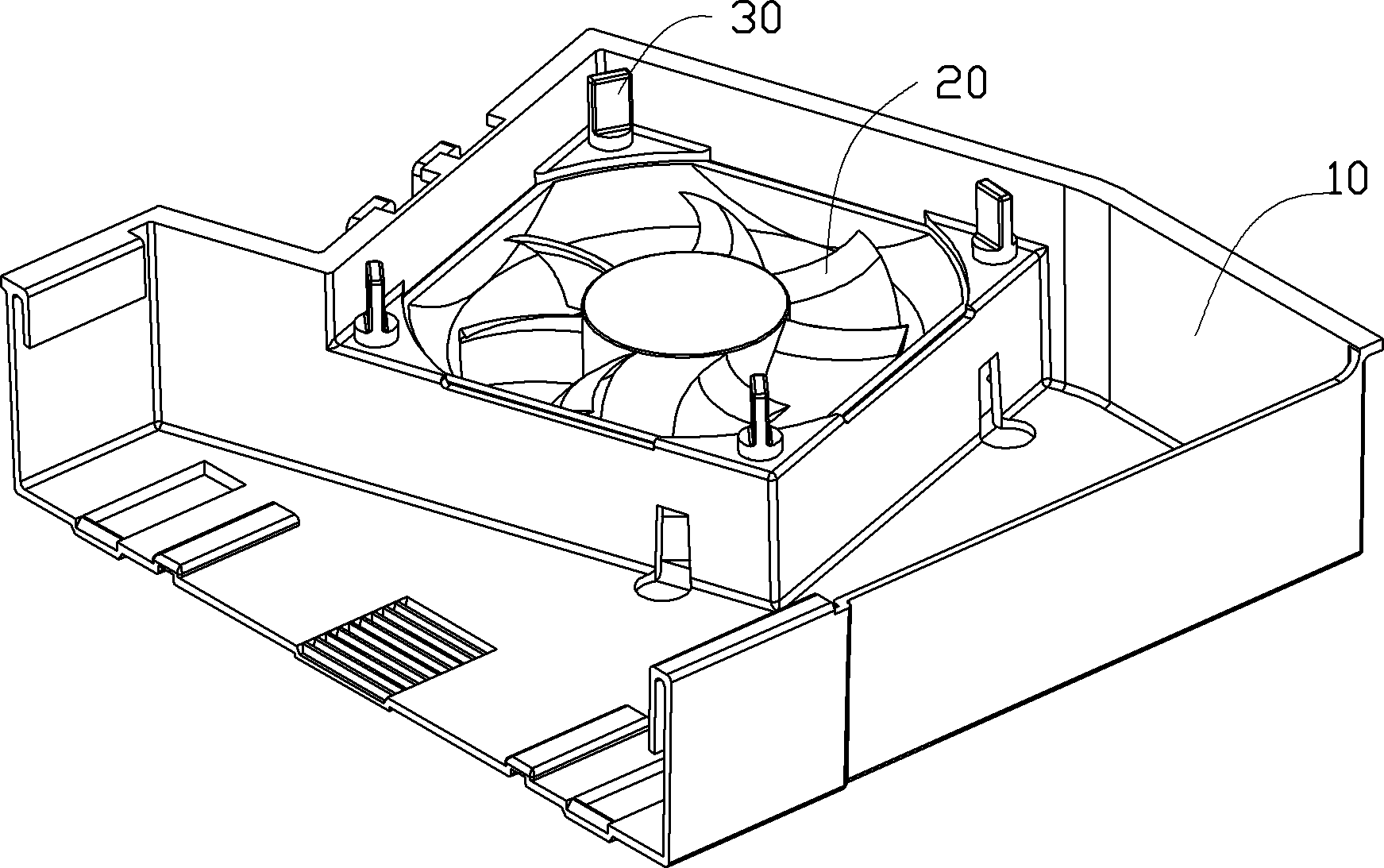
[0047] Such as figure 1 As shown, the fan module in the embodiment provided by the present invention includes a fixing frame 10 , a fan 20 and a fixing member 30 locking and fixing the fixing frame 10 and the fan 20 .

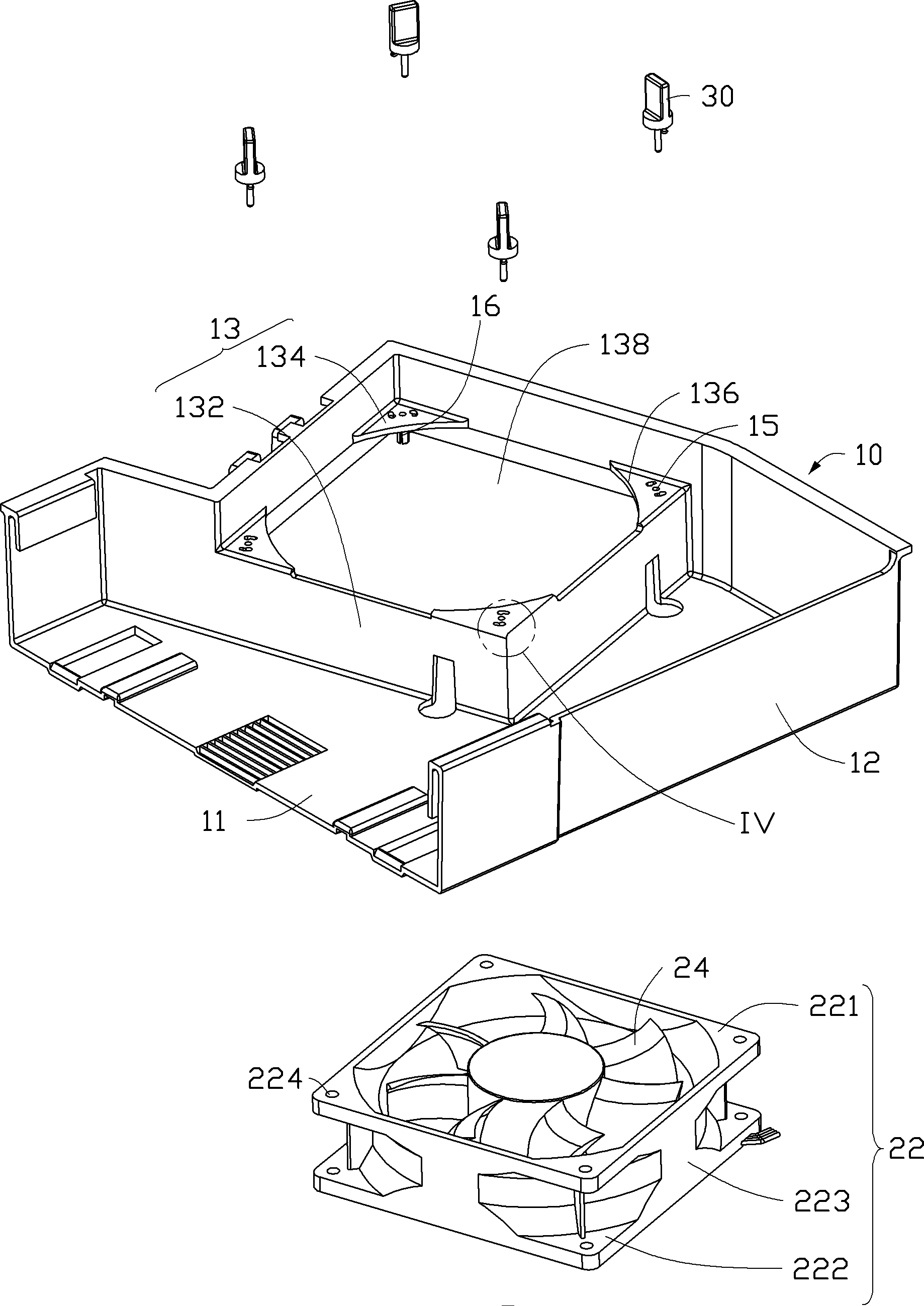
[0048] see figure 2 , the fan 20 includes a fan frame 22 and fan blades 24 accommodated in the fan frame 22 . The fan frame 22 is a hollow rectangle, which includes an upper end surface 221 , a lower end surface 222 and an annular side surface 223 connected between the upper end surface 221 and the lower end surface 222 . The outer contours of the upper end surface 221 and the lower end surface 222 are both square, and the four corners of the upper end surface 221 and the lower end surface 222 are respectively provided with connecting holes 224 . The fan 20 is an axial flow fan, and the centers of the upper end surface 221 and the lower end surface 222 respectively form an air inlet and an air outlet aligned in the axial direction.

[0049] Please also see ...


PUM


Abstract

The invention discloses a fan module which comprises a fixing frame, a fan and a fixing component, wherein the fixing component is used for fixing the fixing frame and the fan through locking; one of the fixing frame and the fan is provided with a plurality of positioning parts, and the other one of the fixing frame and the fan is provided with a connecting hole; an insertion hole and a spring piece column are arranged on the positioning part, wherein the spring piece column is formed by protruding from an outer edge of the insertion hole; the spring piece column is provided with a spring hole which penetrates through the inside of the spring piece column; the spring hole has different diameters in the axial direction; the spring piece column is arranged in the connecting hole in a penetrating way; the fixing component comprises a positioning column; and the positioning column penetrates from the insertion hole into the spring hole, so that a part of the spring piece column, which has a smaller diameter, deforms outwards in the radial direction so as to be clamped in the connecting hole. Therefore, the fan module is simple in the mounting process, convenient in operation and is available for fast demounting.

Description

technical field [0001] The invention relates to a fan module, in particular to a fan module used for heat dissipation of electronic components. Background technique [0002] With the rapid development of the electronic industry, the computing speed of electronic components such as the central processing unit has been greatly increased, and the heat generated by them has also increased sharply. How to dissipate the heat of electronic components to ensure their normal operation has always been an issue in the industry. issues of importance. In order to effectively dissipate the heat generated by the CPU during operation, the industry usually installs a radiator on the surface of the CPU, and installs at least one fan on the top of the radiator. The airflow generated by the fan blows to the radiator to promote heat dissipation. In this way, the temperature of the central processing unit itself is maintained within the normal operating range. [0003] At present, the usual met...

Claims


Application Information

Patent Timeline
Patent Type & Authority Applications(China)
IPC IPC(8): H05K7/20
CPCF04D29/601F01D25/28F04D25/0613H05K7/20172
Inventor 冯锦松何兴华
Owner FU ZHUN PRECISION IND SHENZHEN
Why Eureka
Try Eureka