
Extrusion device

A tool, extrusion direction technology, used in packaging, devices for coating liquid on surfaces, distribution devices, etc., can solve the problems of ending the operation process, limiting the adjustment stroke, inaccuracy, etc.

Inactive Publication Date: 2012-08-01
HILTI AG
View PDF7 Cites 3 Cited by
  • Summary
  • Abstract
  • Description
  • Claims
  • Application Information

AI Technical Summary

Problems solved by technology

A mechanical stop is known from the prior art, which is fixed on the piston rod and moves towards a stop on the housing side to limit the adjustment travel
The disadvantage of this stop is that after each dosing process, this stop has to be recalibrated or set, so that the work cannot be carried out quickly and in a time-saving manner.
On the other hand, due to the inaccuracy caused by repeated settings, the precise dosing of engineering materials cannot be guaranteed
In the prior art, the operator has to count the extrusion strokes to roughly determine the extrusion volume, which is imprecise due to eg the dependence of the extrusion volume on the ambient temperature (viscosity difference) and extrusion force
Furthermore, especially with very viscous engineering materials and the high operating forces required for this, the problem arises that the operator cannot immediately realize that the stop has abutted against the housing and that the operation can be terminated Craft up
As a result, deformation and damage of the stop and even of the entire extrusion tool due to the very high forces applied

Method used


Image

  • Extrusion device
  • Extrusion device
  • Extrusion device

Examples


Embodiment Construction

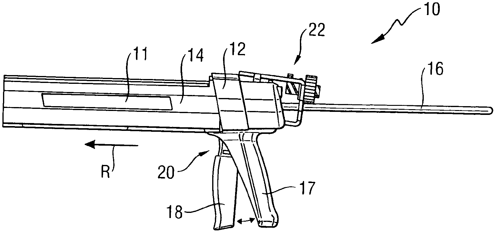
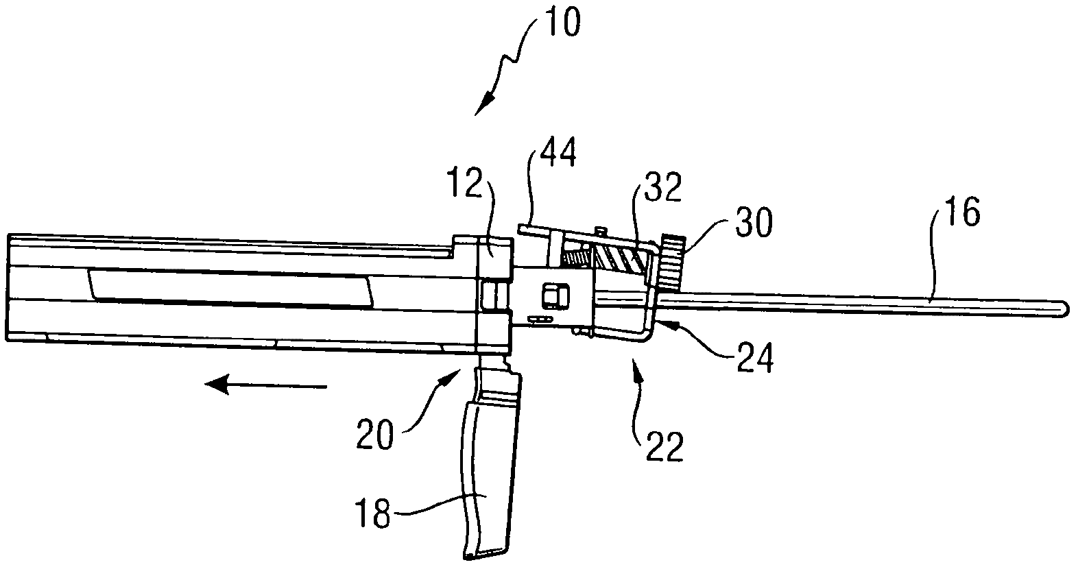
[0028] figure 1 An extrusion tool 10 for a cartridge 11 is shown. Such cartridges have a cylindrical base body filled with a flowable engineering material such as silicone. For very fluid engineering materials, this cartridge is also supported in an additional bag. on one end wall, here means figure 1 On the left end wall in the center, there is an output port for engineering materials. The opposite end wall is formed by a displaceable plunger which is mounted displaceably in the extrusion direction R in the direction of the first end wall in the cylindrical basic body. The volume of the base body is reduced by pushing the plunger in the feed direction R, so that the engineering material can be extruded from the outlet.

[0029] The extrusion tool 10 here has a housing 12 , a holding device 14 which can accommodate the cartridge 12 , and two parallel piston rods 16 , which are displaceably mounted in the housing 12 in the direction of advance R, And it can cooperate with ...


PUM


Abstract

An extrusion device (10) for cartridges includes at least one piston rod (16), an advancer (20) that can be coupled incrementally to the piston rod (16) in order to move the piston rod (16) in a dispensing direction (R), and it also includes a selectively adjustable controller (22) for the variable pre-selection of the path of travel (D) of the piston rod (16) that, once it has traversed the pre-selected path of travel, uncouples the advancer (20) from the piston rod (16).

Description

technical field [0001] The invention relates to an extrusion tool for a cartridge comprising at least one piston rod and a feed device for the piston rod. Background technique [0002] Such extrusion tools are used, for example, in the construction sector to extrude materials from cartridges filled with silicone or other liquid or viscous engineering materials. Such cartridges usually have a cylindrical base body with an outlet opening arranged in one end wall. The opposite end wall is formed by a plunger which is displaceable in the cylindrical main body, so that by displacing this end wall the volume of the cartridge can be changed and the contents of the cartridge can thus be extruded through the outlet opening. Extrusion tools enable precise dosing (dosing) and accurate coating of various engineering materials. Typically, extrusion tools have a piston arranged on a piston rod, which acts on a plunger and which can be pressed against the outlet opening in order to extru...

Claims


Application Information

Patent Timeline
Patent Type & Authority Applications(China)
IPC IPC(8): B05C17/01B65D83/76
CPCB05C17/0123B05C17/00596B05C17/0052
Inventor R·施特罗贝尔-施密特C·黑弗勒P·奥斯特迈尔
Owner HILTI AG
Learn More