Cage type cotton removing and tiny dust removing machine

A technology for fine dust and cotton cleaning, applied in the direction of fiber opening and cleaning machine, etc., can solve the problems of high drop loss rate of spinnable fibers, inability to remove fine dust, poor dust removal effect, etc., to achieve efficient and sufficient dust removal work, saving Maintenance cost, effect of reducing quantity

Inactive Publication Date: 2012-08-01
刘伟
View PDF0 Cites 2 Cited by
  • Summary
  • Abstract
  • Description
  • Claims
  • Application Information

AI Technical Summary

Problems solved by technology

However, the currently used dust removal machines generally have poor dust removal effect, and cannot remove all kinds of dust in the raw cotton, which brings potential d

Method used


Image

  • Cage type cotton removing and tiny dust removing machine
  • Cage type cotton removing and tiny dust removing machine
  • Cage type cotton removing and tiny dust removing machine

Examples


example 1

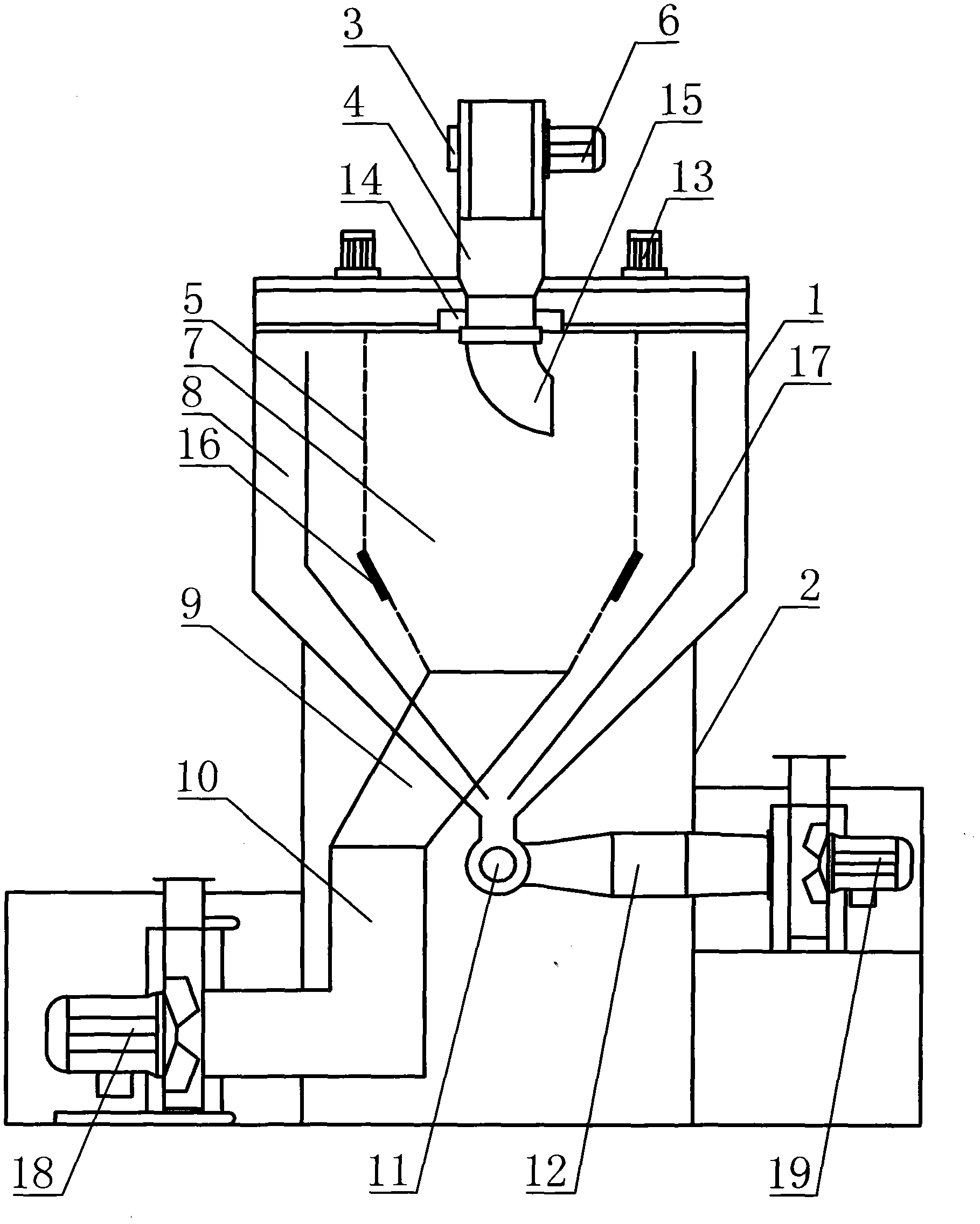
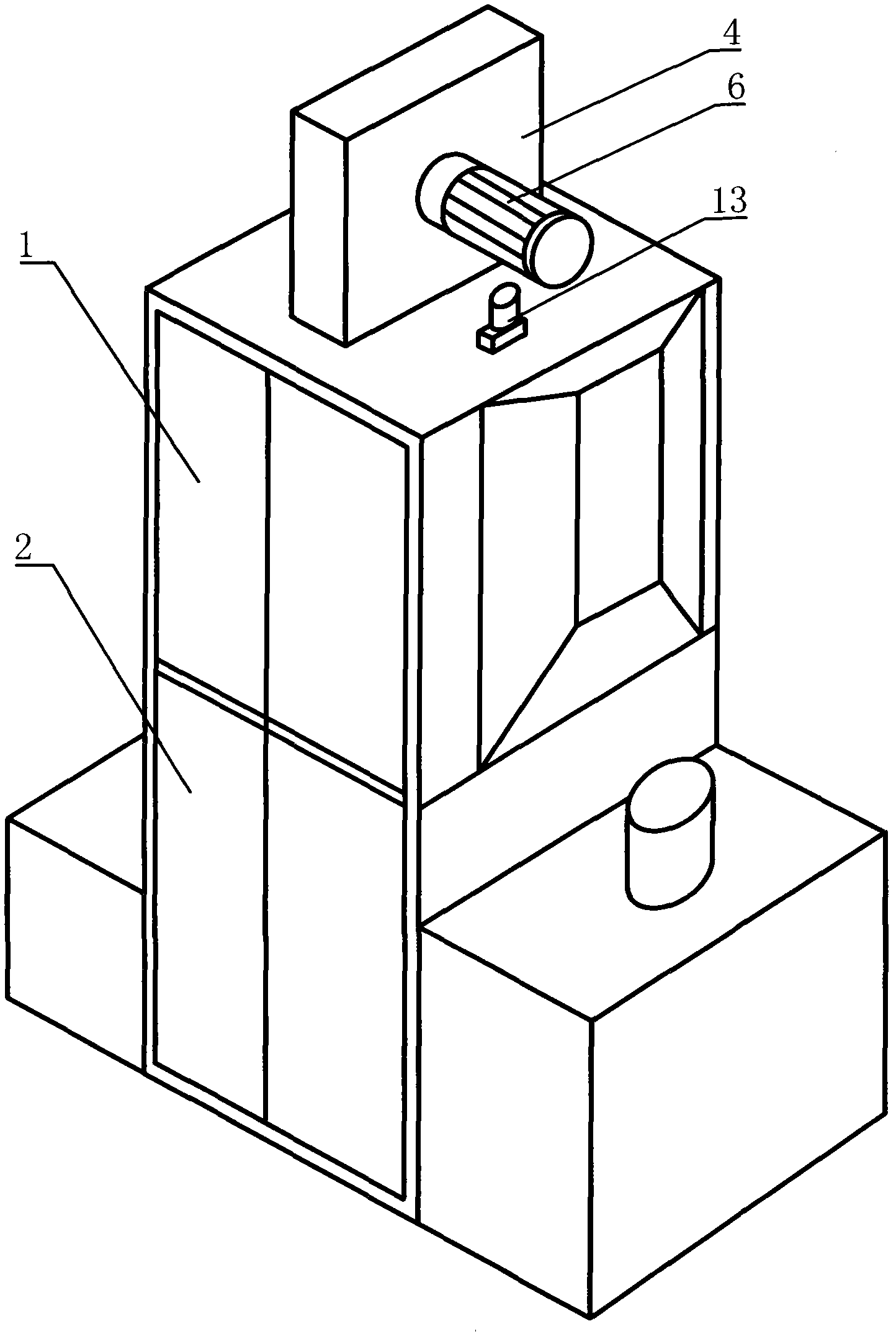
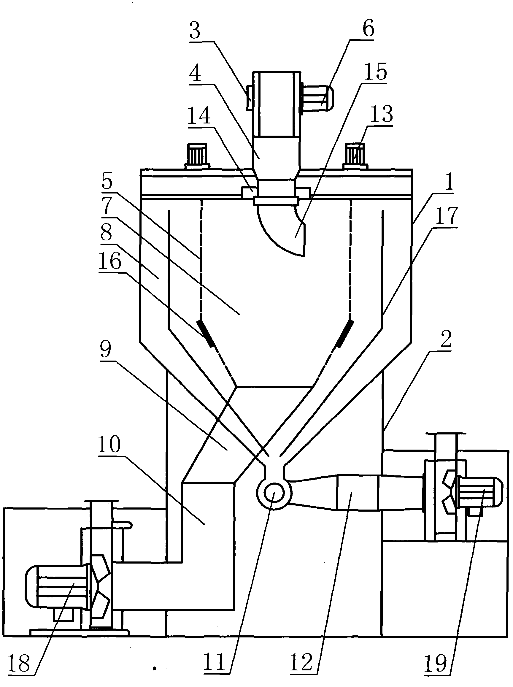
[0019] The cage-type cotton cleaning and dust removal machine of the present invention includes a box body, and the box body is divided into upper and lower parts, the upper part is the upper box body 1, and the lower part is the lower box body 2; the raw cotton tube 4 is arranged on the upper At the center of the top of the box body 1, one side is provided with a raw cotton inlet 3, and the side corresponding to the raw cotton inlet 3 is installed with 4 cotton feeding fans 6, and a rotating device is installed at one end port extending into the upper box body 1; dust cage 5 Set in the center of the upper box 1 and communicate with the top of the upper box 1, the inner space forms a dust filter chamber 7; the dust collection chamber 8 is formed between the inner wall of the upper box 1 and the dust removal cage 5; the middle section collects cotton The chamber 9 is installed on the top of the lower box 2 and connected with the dust filter chamber 7; the cotton outlet pipe 10 i...

example 2

[0022] Cage type cotton cleaning and dust removal machine of the present invention, as figure 1 , figure 2 As shown, the rotating device includes a rotating motor 13, a rotating bearing 14, a rotating elbow 15, and a rotating nozzle. The rotating motor 13 is symmetrically installed on both sides of the top of the upper box body 1; the rotating elbow 15 rotates The tube bearing 14 is installed at the outlet end of the raw cotton tube 4; the rotary nozzle is arranged on the rotary elbow 15. When the raw cotton enters the raw cotton pipe 4, turn on the rotating motor 13 to drive the rotating elbow 15 to rotate 360°, and spray the raw cotton evenly to the dust removal cage 5 through the rotating nozzle while rotating. This method is conducive to efficient and sufficient removal. It works with fine dust, and can effectively reduce the number of neps, realize the effect of evenly distributing raw cotton, and improve the utilization rate of the dust removal cage.

[0023] The dedu...


PUM


Abstract

The invention relates to the technical field of textile machines, in particular to a cage type cotton removing and tiny dust removing machine, which has a good tiny dust removing effect and is high in cotton discharging quality and low in failure rate. The machine comprises an upper box body (1), wherein a raw cotton inlet pipe (4) of which one side is provided with a raw cotton inlet (3) is arranged in the center of the top of the upper box body, and a dust removing cage (5) which is communicated with the top of the upper box body (1) is arranged in the internal center of the upper box body; a cotton inlet fan (6) is arranged on one side of the raw cotton inlet pipe (4); a port at one end of the raw cotton inlet pipe, which is extended into the upper box body, is provided with a rotating device; a tiny dust filtering chamber (7) is formed in an internal space of the dust removing cage (5); a tiny dust collecting chamber (8) is formed between the tiny dust filtering chamber (7) and the inner wall of the upper box body (1); a middle section cotton collecting chamber (9) which is connected with the tiny dust filtering chamber (7) is formed on the top of a lower box body (2); and a cotton discharging pipe (10) connected with the outlet of the middle section cotton collecting chamber (9), a dust collecting groove (11) connected with the outlet of the tiny dust collecting chamber (8) and a dust discharging air pipe (12) connected with the outlet of the dust collecting groove (11) are arranged at the bottom of the lower box body (2).

Description

technical field [0001] The invention relates to the technical field of textile machinery, in particular to a cage type cotton cleaning and dust removal machine. Background technique [0002] Cotton opening and cleaning is an important process in textile production. A series of spinning processes are required to process raw cotton or various staple fibers into yarns, and the process of opening and cleaning cotton is the first process of the spinning process. The combined opening and cleaning machine in this process completes the following tasks: first, loosening, that is, through the tearing and striking action of corner nails, thugs in each stand-alone machine of the combined opening and cleaning machine, the compressed block fibers in the cotton bale are loosened into Small cotton bundles with a weight of 0.3 to 0.5g create conditions for impurity removal and mixing, and prepare for separation into single fibers; followed by impurity removal, that is, removing 50% to 60% of...

Claims


Application Information

Patent Timeline
IPC IPC(8): D01G9/14
Inventor 刘伟
Owner 刘伟
Why Eureka
Try Eureka