Fuel Injection Valve

A fuel injection valve and fuel injection technology, applied in fuel injection devices, charging systems, engine components, etc., can solve the problems of uneven swirl strength in the circumferential direction and damage to the symmetry of swirl strength

Inactive Publication Date: 2012-08-01
HITACHI AUTOMOTIVE SYST LTD
View PDF4 Cites 5 Cited by
  • Summary
  • Abstract
  • Description
  • Claims
  • Application Information

AI Technical Summary

Problems solved by technology

[0008] In particular, when the cross-sectional shape of the swirl passage is rectangular and the passage height along the direction of the center axis of the swirl is low, the symmetry (uniformity) of the swirl strength will be impaired in the swirl chamber or the fuel injection hole.
In this case, the outflow of fuel on the center side of the swirl chamber in the flow passage section of the passage for swirl reaches the inlet of the fuel injection hole earlier than that on the outer peripheral side, so that the fuel in the swirl chamber and the outlet of the fuel injection hole Intensity becomes uneven circumferentially

Method used


Image

  • Fuel Injection Valve
  • Fuel Injection Valve
  • Fuel Injection Valve

Examples


Embodiment 1

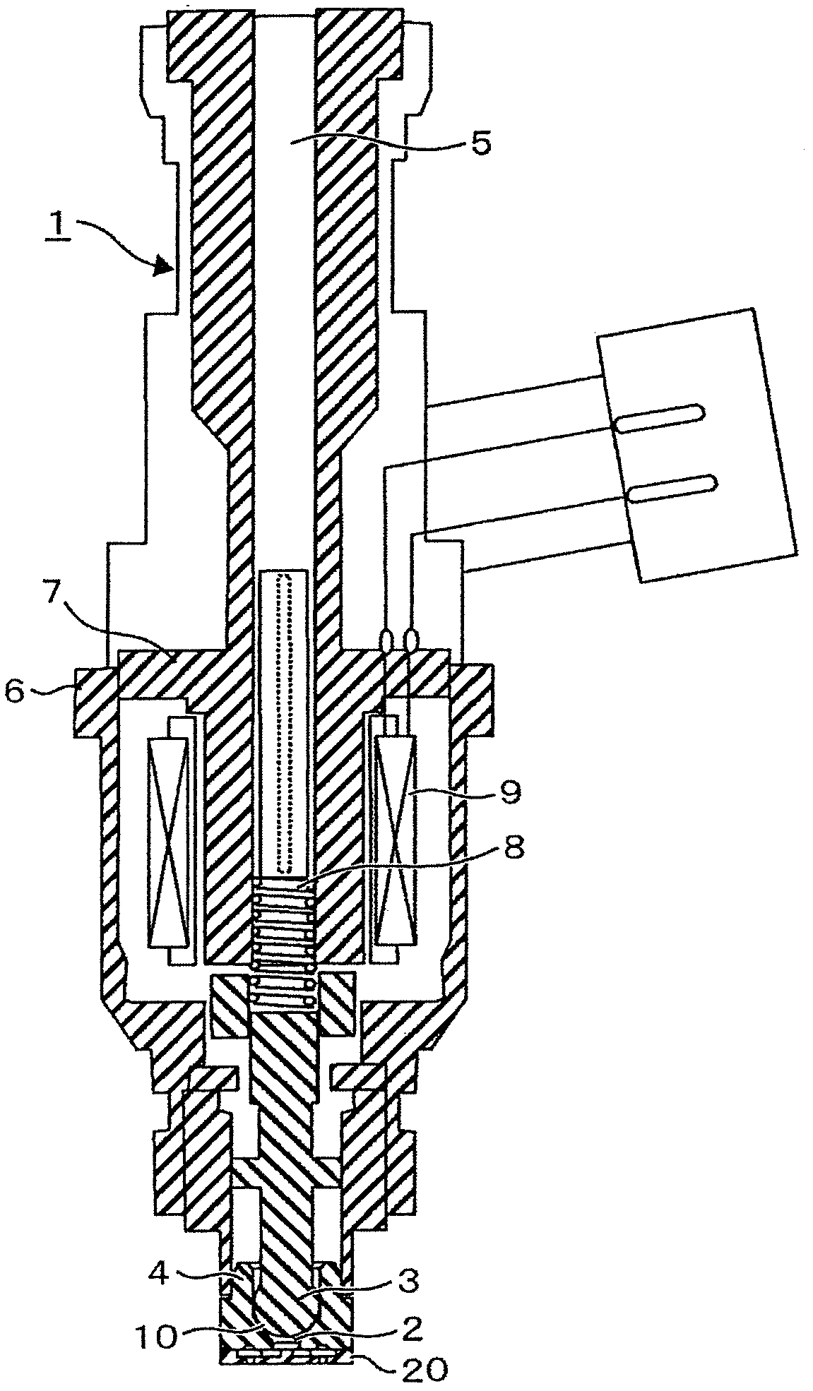
[0040] Below, refer to Figure 1 to Figure 6 , the fuel injection valve according to the first embodiment of the present invention will be described in detail.

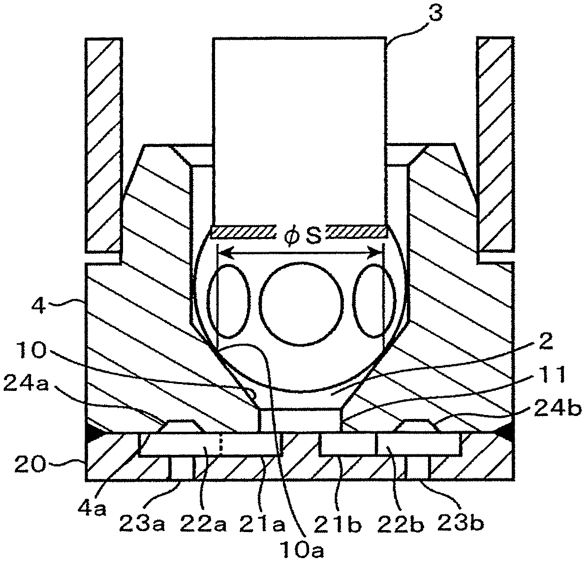
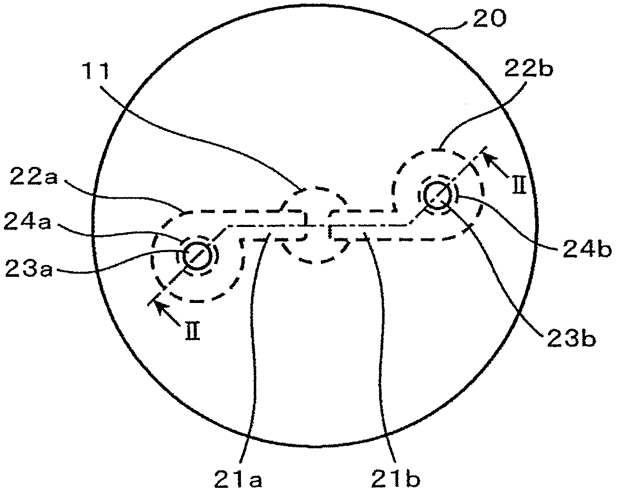
[0041] figure 1 It is a longitudinal cross-sectional view along the direction of the valve axis of the fuel injection valve according to the first embodiment of the present invention. figure 2 It is an enlarged longitudinal sectional view of the lower end portion of the nozzle body in the fuel injection valve according to the first embodiment. image 3 This is a view of the orifice plate located at the lower end of the nozzle body in the fuel injection valve according to the first embodiment viewed from below. 4 is a diagram for explaining a recess (bumper) according to the first embodiment, and is a diagram for explaining a positional relationship between a swirl chamber and a fuel injection hole. Figure 5 It is a figure for demonstrating the flow state (expressed by the velocity vector) in the swirl chamber con...

Embodiment 2

[0095] Below, refer to Figure 7 , the fuel injection valve according to the second embodiment of the present invention will be described in detail. Figure 7 It is a diagram for explaining the structure of the intermediate plate 30 located at the lower end portion of the nozzle body 4 in the fuel injection valve according to the second embodiment of the present invention.

[0096] The difference from the fuel injection valve according to the first embodiment is that an intermediate plate 30 is sandwiched between the nozzle body 4 and the orifice plate 20 , and a surface 30 a of the intermediate plate 30 facing the orifice plate 20 is provided There are recessed parts (buffer parts) 24a, 24b. The intermediate plate 30 and the orifice plate 20 can be fixed to the nozzle body 4 after alignment, assembly and adjustment in advance. Since the assembly adjustment is performed in advance, the characteristics of the spray shape and injection amount can be measured in the component a...


PUM


Abstract

There is provided a fuel injection valve, in which uniformity in swirl intensity in a peripheral direction of a swirl fuel is heightened. A fuel injection valve comprises a valve element (3) and a valve seat (10), which cooperate to open and close a fuel passage to perform injection of a fuel and stoppage of injection, a nozzle body (4) having the valve seat (10), a swirl passage (21) provided downstream of a seat portion (10a), on which the valve element (3) and the valve seat (10) contact with each other, and a swirl chamber (22), to which the swirl passage (21) and a fuel injection port (23) are connected, and a recess (buffer) (24) for enlargement of the swirl chamber (22) in volume is provided on a wall surface portion (4a) of the swirl chamber (22) opposed to the fuel injection port (23).

Description

technical field [0001] The present invention relates to a fuel injection valve used in an internal combustion engine, and more particularly to a fuel injection valve having a plurality of fuel injection holes and injecting swirling fuel from each fuel injection hole to improve atomization performance. Background technique [0002] A fuel injection valve described in Patent Document 1 is known as a conventional technique for promoting atomization of fuel injected from a plurality of fuel injection holes by using a swirling flow. [0003] In this fuel injection valve, a transverse passage and a swirl chamber are formed between a valve seat member in which a downstream end of a valve seat cooperating with a valve core is opened to a front end surface and an injection plate. , the injection plate is engaged with the front end surface of the valve seat member, the transverse passage communicates with the downstream end of the valve seat, the vortex chamber is formed by opening th...

Claims


Application Information

Patent Timeline
Patent Type & Authority Applications(China)
IPC IPC(8): F02M61/18
CPCF02M61/1853F02M61/162
Inventor 冈本良雄安川义人石川正典小林信章斋藤贵博前川典幸
Owner HITACHI AUTOMOTIVE SYST LTD
Why Eureka
Try Eureka