Supercharge Your Innovation With Domain-Expert AI Agents!

High-temperature high-pressure pneumatic control automatic pressure relief valve

A high-temperature, high-pressure, automatic venting technology, which is applied in safety valves, balance valves, valve devices, etc., can solve the problems of large difference in discharge pressure, fluctuation of set pressure, poor stability, etc., and achieve the effect of small difference and accurate set pressure

Inactive Publication Date: 2012-08-01
TIANZHENG VALVE
View PDF6 Cites 12 Cited by
  • Summary
  • Abstract
  • Description
  • Claims
  • Application Information

AI Technical Summary

Problems solved by technology

Its main disadvantage is that the spring has different elastic coefficients under different temperature conditions, so there are large fluctuations in the set pressure under high temperature conditions, the accuracy of the set pressure is low, the stability is poor, and the difference between the discharge pressure and the set pressure is large. Not suitable for use in containers or piping systems that require high accuracy of set pressure

Method used


Image

  • High-temperature high-pressure pneumatic control automatic pressure relief valve
  • High-temperature high-pressure pneumatic control automatic pressure relief valve

Examples


Embodiment Construction

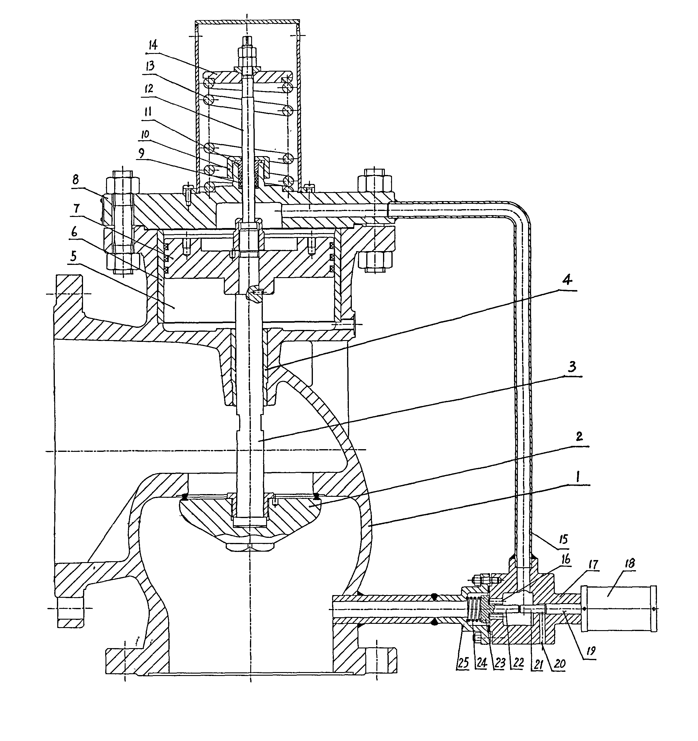
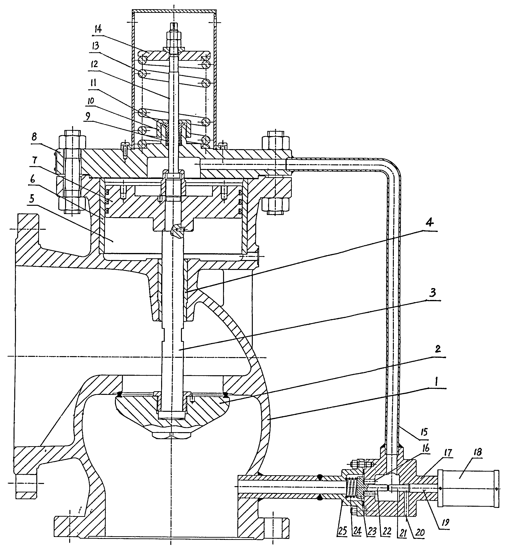
[0009] Such as figure 1 The high-temperature and high-pressure air-controlled automatic pressure relief valve shown includes a main valve and a pilot valve. The main valve includes a valve body 1, a valve disc 2, a valve stem 3, and a valve cover 8. The valve body 1 has an inlet and an outlet, and the valve stem 3 The lower end is fixedly connected with the disc 2, and the upper plane of the disc 2 has a sealing surface that cooperates with the inlet channel side of the valve body 1, that is, the disc 2 is located in the inlet channel of the valve body 1, and the sealing surface of the disc 2 is in contact with the inlet channel of the valve body 1. The sealing surface of the valve seat between the outlet passage and the outlet passage cooperates and seals each other. The upper part of the valve body 1 is formed with a piston chamber 5, the upper end of the valve rod 3 passes through the valve body 1 and is fixedly connected with the piston 7 in the piston chamber 5, and a pis...


PUM


Abstract

The invention relates to a high-temperature high-pressure pneumatic control automatic pressure relief valve, which comprises a main valve and a pilot valve. The main valve comprises a valve body, a valve clack, a valve rod and a valve cover. The high-temperature high-pressure pneumatic control automatic pressure relief valve is characterized in that: a piston cavity is formed on the upper part of the valve body; the upper end of the valve rod penetrates through the valve body, and is fixedly connected with a piston in the piston cavity; the flat area of the upper end face of the piston is larger than that of the lower end face of the valve clack; the pilot valve adopts a pneumatic control valve which comprises a pilot valve body, a pilot valve clack and a pneumatic device; an inlet of the pilot valve body is communicated with an inlet of the valve body, and an outlet of the pilot valve body is communicated with the piston cavity on one side of the upper plane of the piston; the pilot valve clack is connected with a transmission shaft of the pneumatic device; an air source control circuit of the pneumatic device is connected in series with a pressure control switch of a pressure sensor which is arranged in an intake vent of the valve body; and a discharge orifice is formed in the pilot valve body. The opening / closing state of the pilot valve is controlled according to a pressure signal of the pressure sensor by the pneumatic device. The high-temperature high-pressure pneumatic control automatic pressure relief valve has the advantages of accurate and stable set pressure, discharge pressure equal to the set pressure, and the like, and is applied to a pressure relief protection device of a high-temperature high-pressure vessel.

Description

technical field [0001] The invention relates to the field of valves, in particular to a pressure relief valve. The invention is suitable for the pressure relief protection device of high-temperature and high-pressure vessels such as steam and nitrogen. Background technique [0002] At present, the pressure relief valves used in pipelines and containers generally adopt the pilot-operated safety valve structure, and the pilot valve is used to control the main valve. The pilot valve is a spring-type safety valve with an independent pressure relief function. When the system pressure reaches the set pressure, the pilot valve opens to release the medium in the main valve piston chamber, and the main valve spring pushes the disc to open. For example, the built-in pilot safety valve whose publication number is CN102313052A includes a main valve and a pilot valve. , the pilot valve is installed in the inner hole of the main valve limit sleeve. When the medium pressure exceeds the ...

Claims


Application Information

Patent Timeline
Patent Type & Authority Applications(China)
IPC IPC(8): F16K17/10
Inventor 徐文娴
Owner TIANZHENG VALVE
Features
  • R&D
  • Intellectual Property
  • Life Sciences
  • Materials
  • Tech Scout
  • Unparalleled Data Quality
  • Higher Quality Content
  • 60% Fewer Hallucinations
Learn More