Pump-free jet refrigerating machine
A spray type and refrigerator technology, applied in refrigerators, refrigeration components, machines using refrigerant evaporation, etc., can solve the problems of bulky equipment, poor feasibility, low pressure, etc., and achieve simple equipment structure and long service life , low cost effect
- Summary
- Abstract
- Description
- Claims
- Application Information
AI Technical Summary
Problems solved by technology
Method used
Image

Examples
Embodiment 1
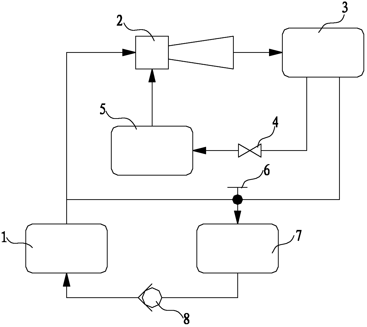
[0026] Such as figure 1 As shown, a pumpless ejector refrigerator, the first ejector 2 is sequentially connected in series with the condenser 3, the throttling element 4, and the evaporator 5 to form a circuit; the three-way valve 6 is sequentially connected with the first liquid storage tank 7, the first The one-way valve 8 and the generator 1 are connected in series to form a circuit; the generator 1 and the first injector 2 are provided with a communicating pipeline; the condenser 3 and the three-way valve 6 are provided with a communicating pipeline. The height of the condenser 3 is higher than that of the first liquid storage tank 7 , and the height of the first liquid storage tank 7 is higher than that of the generator 1 . The three-way valve 6 includes three ports of port I, port II and port III.
[0027] The specific connection relationship of each element in the refrigerator in this embodiment is:
[0028] The working fluid inlet of the first injector 2 communicate...
Embodiment 2
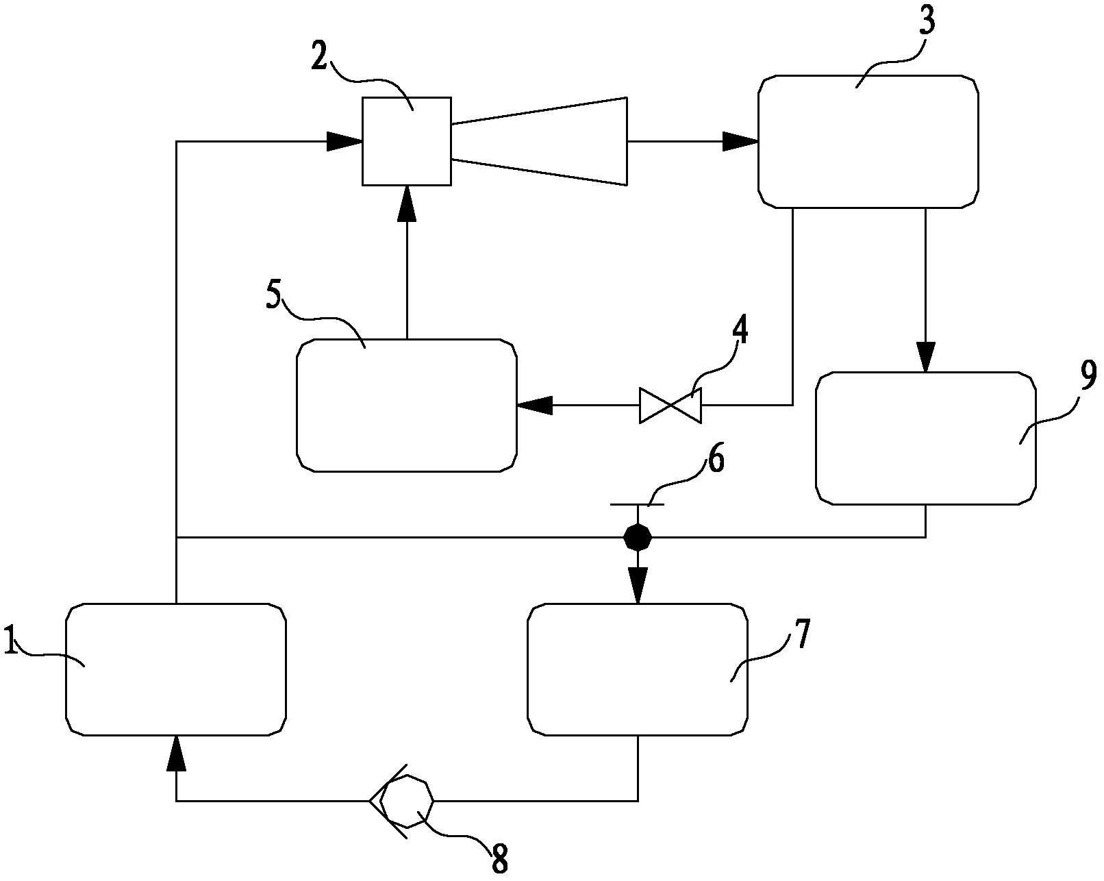
[0033] Such as figure 2 As shown, a pumpless ejector refrigerator is different from the refrigerator structure in Embodiment 1 in that the pipeline between the condenser 3 and the port 1 of the three-way valve 6 is provided with a second liquid storage tank 9. The height of the second liquid storage tank 9 is higher than that of the first liquid storage tank 7 . The specific connection relationship is: the working medium inlet of the second liquid storage tank 9 is connected with the working medium outlet of the condenser 3 , and the working medium outlet of the second liquid storage tank 9 is connected with port I of the three-way valve 6 . The rest of the connections are the same as in Example 1.
[0034] The working process of the circulating working medium in the refrigerator in this embodiment is:
[0035] When the liquid level in the first liquid storage tank 7 is lower than the set value, the three-way valve 6 switches to position 1, the second liquid storage tank 9...
Embodiment 3
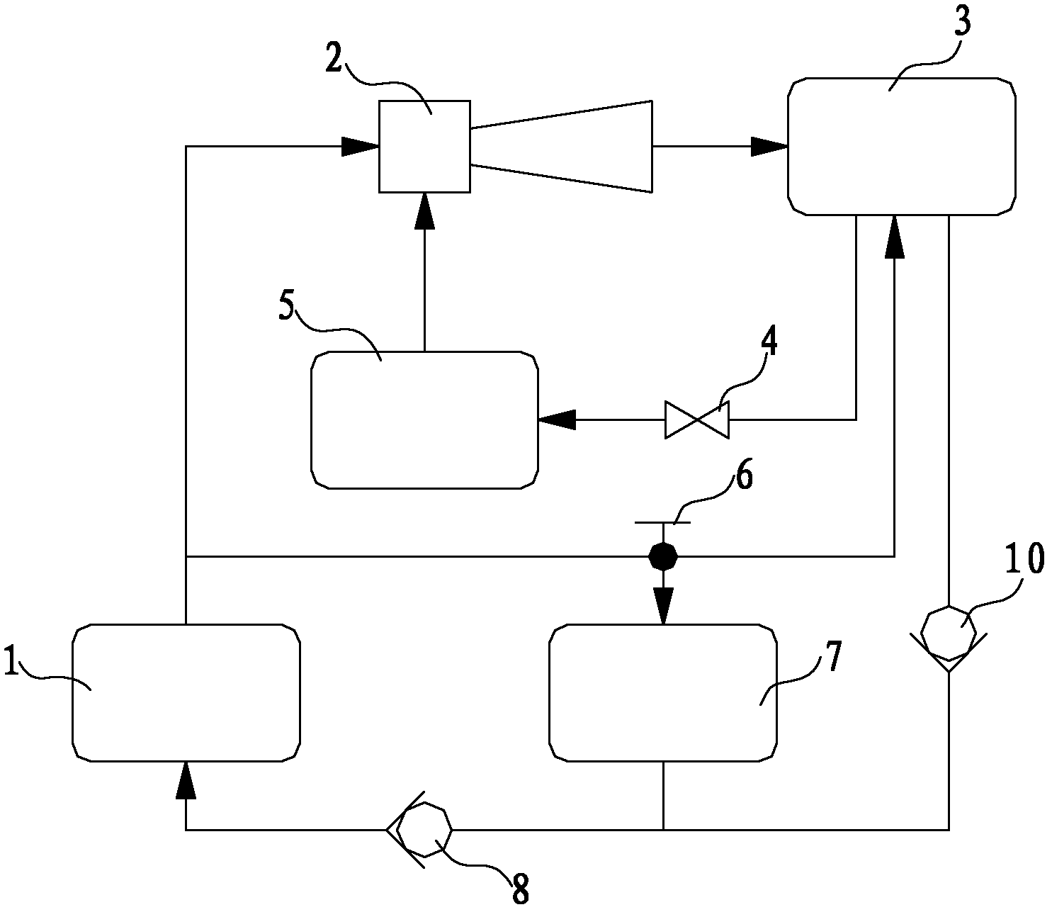
[0037] Such as image 3 As shown, a pumpless ejector refrigerator differs from the refrigerator structure in Embodiment 1 in that a second check valve is connected in series between the working medium outlet of the condenser 3 and the first liquid storage tank 7 10. The specific connection relationship is: the working medium outlet of the condenser 3 communicates with the working medium inlet of the second one-way valve 10, and the working medium outlet of the second one-way valve 10 communicates with the working medium outlet of the first liquid storage tank 7.
[0038] The working process of the circulating working medium in the refrigerator in this embodiment is:
[0039] When the liquid level in the first liquid storage tank 7 is lower than the set value, the three-way valve 6 is switched to position 1, the condenser 3 communicates with the first liquid storage tank 7, and the generator 1 and the first liquid storage tank 7 do not communicate. , the high-temperature and h...
PUM
 Abstract
Description
Claims
Application Information
 - Generate Ideas
- Intellectual Property
- Life Sciences
- Materials
- Tech Scout
- Unparalleled Data Quality
- Higher Quality Content
- 60% Fewer Hallucinations
Browse by: Latest US Patents, China's latest patents, Technical Efficacy Thesaurus, Application Domain, Technology Topic, Popular Technical Reports.
© 2025 PatSnap. All rights reserved.Legal|Privacy policy|Modern Slavery Act Transparency Statement|Sitemap|About US| Contact US: help@patsnap.com