Magnetic induction rotation speed measuring device
A speed measurement and magnetic induction technology, applied in the field of electronics, can solve problems such as structure acquisition, and achieve the effects of simple cost, simple structure and easy modification
- Summary
- Abstract
- Description
- Claims
- Application Information
AI Technical Summary
Problems solved by technology
Method used
Image
Examples
Embodiment 1
[0027] Such as figure 1 As shown, the magnetic induction rotational speed measuring device of the embodiment of the present invention includes: a magnetic body 1 fixed on a rotating body; and a magnetic induction mechanism 2 for detecting the rotational speed of the magnetic body.
[0028] The embodiment of the present invention can adopt a simple structure to realize the speed measurement of the rotating object, that is, through the magnetic body fixed on the rotating object, the magnetic induction mechanism that has been used to sense the magnetic body monitors the rotating speed of the rotating object. This structure is not only low in cost, easy to implement, but also easy to improve on existing products.
Embodiment 2
[0030] Furthermore, on the basis of Embodiment 1, this application provides a specific implementation manner. Of course, this implementation is only for the purpose of illustration, rather than limiting the general concept of the present application. Those skilled in the art can understand that any implementation method under the general concept of the application, even if it is not included in the application, should also be within the protection scope of the application.
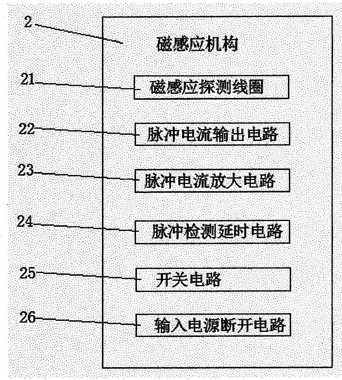
[0031] Specifically, such as figure 2 The magnetic induction mechanism in Embodiment 1 includes: a magnetic induction detection coil 21 fixed on the rotating object side to detect the rotational speed of the magnetic body, a pulse current output that outputs current when the magnetic induction detection coil 21 detects a magnetic body Circuit 22, a pulse detection delay circuit 24 for determining the rotational speed of the rotating object according to the output current of the pulse current output circu...
Embodiment 3
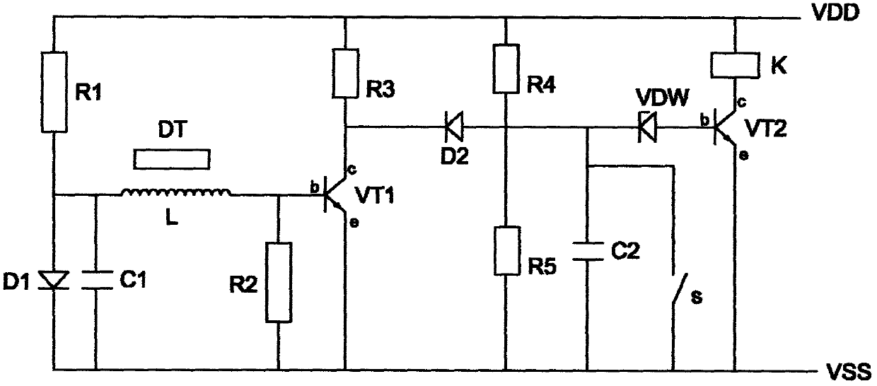
[0037] Such as image 3 As shown, on the basis of Embodiment 1 and Embodiment 2, the present application provides a specific circuit diagram for realizing the general idea of the present application. Certainly, the circuit diagram is only for the purpose of illustration, rather than limiting the general concept of the present application. Those skilled in the art can understand that any circuit structure under the general concept of the present application, even if it is not included in the present application, should also be within the protection scope of the present application.
[0038] Such as image 3 As shown, the magnetic body DT can be a permanent magnet.
[0039] The pulse current amplifying circuit includes: positive voltage VDD, negative voltage VSS, first resistor R1, second resistor R2, third resistor R3, first diode D1, first capacitor C1, second capacitor C2, first Transistor VT1;
[0040] The positive voltage VDD is connected to the anode of the first dio...
PUM
 Abstract
Description
Claims
Application Information
 - R&D Engineer
- R&D Manager
- IP Professional
- Industry Leading Data Capabilities
- Powerful AI technology
- Patent DNA Extraction
Browse by: Latest US Patents, China's latest patents, Technical Efficacy Thesaurus, Application Domain, Technology Topic, Popular Technical Reports.
© 2024 PatSnap. All rights reserved.Legal|Privacy policy|Modern Slavery Act Transparency Statement|Sitemap|About US| Contact US: help@patsnap.com


