
Obtaining method of direct current magnetic biasing hysteresis loop of transformer core material

A technology of DC bias and hysteresis loop, applied in hysteresis curve measurement, magnetic performance measurement, etc., can solve problems such as inconsistency in series excitation methods, inability to separate AC magnetic flux and DC magnetic flux, and error in measurement results

Inactive Publication Date: 2012-08-01
HEBEI UNIV OF TECH
View PDF3 Cites 23 Cited by
  • Summary
  • Abstract
  • Description
  • Claims
  • Application Information

AI Technical Summary

Problems solved by technology

The disadvantage of this method is that the excitation method of the system adopts the parallel loading method of AC excitation and DC excitation, which is inconsistent with the series excitation method when the DC bias problem occurs in the power transformer in the actual online operation, resulting in errors in the measurement results
Even if the system adopts a series excitation method that is consistent with the actual working conditions, since the excitation of the material is a mixture of AC and DC, the AC magnetic flux and DC magnetic flux cannot be separated in the measurement results, and the DC magnetic flux of the silicon steel sheet material still cannot be directly determined from experiments

Method used


Image

  • Obtaining method of direct current magnetic biasing hysteresis loop of transformer core material
  • Obtaining method of direct current magnetic biasing hysteresis loop of transformer core material
  • Obtaining method of direct current magnetic biasing hysteresis loop of transformer core material

Examples


Embodiment 1

[0057]The method for obtaining the DC bias hysteresis loop of the transformer core material 30Q140 cold-rolled grain-oriented silicon steel sheet, the AC operating point of the given transformer core model is U g =459V is applied to the transformer core model at the same time with the given DC bias magnetic field strength as I dc = 0.1A.

[0058] A. The device used to make the method of obtaining the DC bias hysteresis loop of the transformer core material

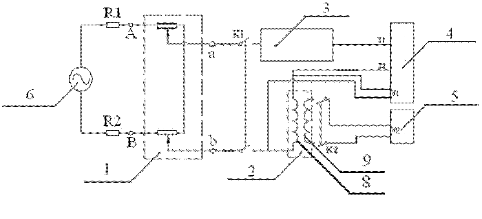
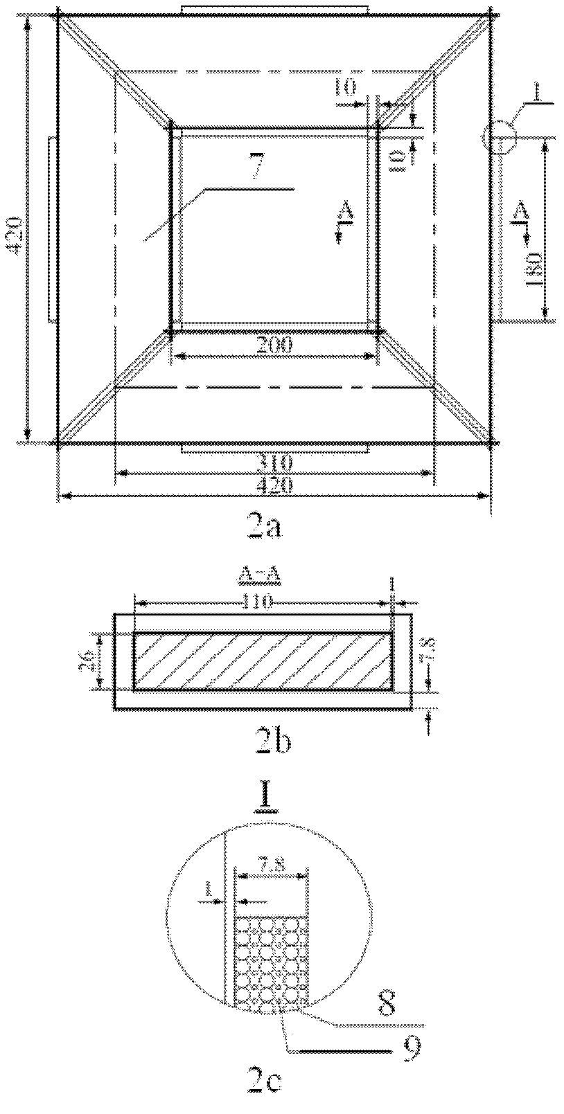
[0059] use figure 1 and figure 2 The embodiment shown constitutes the device used in the method for obtaining the DC bias hysteresis loop of the transformer core material in this embodiment, wherein the transformer core model 2 adopts 45° full oblique joints, two pieces per level and three steps 5mm overlapped stacking process, in order to ensure the accuracy of the experimental measurement results, the excitation coil 8 and the measurement coil 9 are wound close to the transformer laminated core 7 and clamped by insul...

Embodiment 2

[0083] The method for obtaining the DC bias hysteresis loop of the transformer core material 30Q140 cold-rolled grain-oriented silicon steel sheet, the AC operating point of the given transformer core model 2 is U g =27V is applied to the transformer core model 2 at the same time with the DC bias magnetic field strength as I dc = 1A.

[0084] A. The device used to make the method of obtaining the DC bias hysteresis loop of the transformer core material

[0085] With embodiment 1.

[0086] B. Using the device used in the method of obtaining the DC bias hysteresis loop of the transformer core material made by A, follow the steps below to obtain a given AC operating point U g =27V and a given DC bias magnetic field strength I dc = DC bias hysteresis loop of the tested transformer core material when 1A is applied.

[0087] The first step to the fourth step are carried out in full accordance with embodiment 1; in the fifth step to the thirteenth step, except that the given AC o...

Embodiment 3

[0089] The method for obtaining the DC bias hysteresis loop of the transformer core material 30Q140 cold-rolled grain-oriented silicon steel sheet, the AC operating point of the given transformer core model 2 is U g =486V is applied to the transformer core model 2 at the same time with the DC bias magnetic field intensity as I dc = 2A.

[0090] A. The device used to make the method of obtaining the DC bias hysteresis loop of the transformer core material

[0091] With embodiment 1.

[0092] B. Using the device used in the method of obtaining the DC bias hysteresis loop of the transformer core material made by A, follow the steps below to obtain a given AC operating point U g =486V and a given DC bias magnetic field strength I dc = DC bias hysteresis loop of the tested transformer core material when 2A is applied.

[0093] The first step to the fourth step are carried out in full accordance with embodiment 1, and in the fifth step to the thirteenth step, except that the giv...


PUM


Abstract

The invention provides an obtaining method of a direct current magnetic biasing hysteresis loop of a transformer core material, relates to measurement of the hysteresis loop, and has the following steps of manufacturing a device used by the method by using a variable-voltage transformer, a transformer core model, a direct current source, a digital oscilloscope, a power analyzer and a power frequency alternating current power supply, and obtaining any given alternating current working point in the scope of 27 V-486V by using the device according to 13 steps, namely the biasing hysteresis loop of the transformer core material to be measured under the effect of any given direct current magnetic biasing magnetic field intensity in the scope of voltage Ug output by the power frequency alternating current power supply and in the scope of 0.1 A-2A. The obtaining method adopts the mode of alternating current and direct current series connection stimulation same with that when an actual transformer generates direct current magnetic biasing, simulates direct current magnetic flow in an overlapping iron core material under working conditions of the direct current magnetic biasing, and completely meets actual situations when the power transformer has the direct current magnetic biasing. Obtained direct current magnetic biasing hysteresis loop of the transformer core material is close to the true value.

Description

technical field [0001] The technical scheme of the invention relates to the measurement of the hysteresis curve, in particular to the method for obtaining the DC bias hysteresis loop of the transformer core material. Background technique [0002] With the continuous development of my country's UHVDC transmission technology, the problem of transformer DC bias has become increasingly prominent, and has become an urgent problem to be solved in engineering practice. It is very necessary for transformer manufacturers, power system management and construction departments to study the influence of DC bias on AC transformers, which has attracted the attention of transformer designers and researchers at home and abroad. [0003] The transformer DC bias phenomenon refers to the DC magnetic flux in the transformer core for some reason, which makes the transformer core present positive and negative half-cycle asymmetrical saturation and a series of electromagnetic effects caused by it. ...

Claims


Application Information

Patent Timeline
Patent Type & Authority Applications(China)
IPC IPC(8): G01R33/14
Inventor 赵志刚刘福贵李永建刘兰荣张俊杰程志光汪友华
Owner HEBEI UNIV OF TECH
Learn More